
In the early 1970s, this line of thinking prompted Bennett to come up
with ways to beat the Landauer limit: by introducing reversible computation.
The gates we have studied so far, such as AND and XOR, are intrinsically
irreversible since they are two-one functions. An n → m function can, however,
be implemented reversibly if it is embedded in a reversible n + m → m + n
function.
The additional m inputs take certain fixed values, and are referred to
as ancilla bits, while the extra n outputs are ignored. These are sometimes
referred to as garbage bits.
(x, 0) 7−→
f(x), g(x)
. (6.13)
. ↓ ↓ &
input ancilla output garbage
The advantage of reversibility is that the entire process can be run in
reverse after storing (copying) the answers, so that all the bits are returned
to their original states. The garbage is thus effectively recycled! The circuit
diagram for such a reversible implementation is given in Figure 6.5.
f
m bit output f(x)
n bit input x
0
n (ignore)
m ancillary bits 0
0
FIGURE 6.5: Reversible implementation of an irreversible function
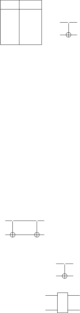
The function may be reversible only if the circuit to compute it is built
out of reversible gates. NOT is a reversible 1-bit gate. A reversible 2-bit gate
is the CNOT or controlled-NOT gate. This classic gate acts as NOT on the
1
k
B
= 1.38 × 10
−23
J/K. This constant appears in the relationship between energy and
temperature at the level of particle constituents of a thermodynamic system.
112 Introduction to Quantum Physics and Information Processing
second (target) input bit if the first (control) bit is set to 1; otherwise it leaves
it unchanged. The truth table and circuit representation is:
CNOT:
x y x
0
y
0
0 0 0 0
0 1 0 1
1 0 1 1
1 1 1 0
x
•
x
y
x ⊕ y
(6.14)
Here the top bit is the control bit. The filled circle on the connecting wire
between the two bits represents control by the value 1. The lower bit is the
target bit.
Exercise 6.3. Check that the matrix representation for the CNOT gate is
C =
1 0 0 0
0 1 0 0
0 0 0 1
0 0 1 0
.
Now the CNOT gate is a reversible implementation of the XOR gate. You
can see that the second output y
0
represents the XOR of the inputs. So if we
ignore the first output, we have here a reversible XOR gate:
XOR : (x, y) 7→ (x, x ⊕ y). (6.15)
This is reflected in the circuit symbol for CNOT, where the target bit is shown
with an ⊕ symbol acting on it, controlled by the first bit.
It is easy to see that this gate is the inverse of itself: if a second CNOT
acts on the outputs of one CNOT, we get back the inputs to the first CNOT.
(Note however that a reversible gate is not necessarily its self-inverse.)
x
•
x
•
x
y
x ⊕ y
x ⊕ x ⊕ y = y
The CNOT gate can be used to reversibly embed several other useful gates
such as the COPY gate and the SWAP gate:
COP Y : (x, 0) 7→ (x, x)
x
•
x
0
x
(6.16)
SW AP : (x, y) 7→ (y, x)
x
S
y
y
x
(6.17)
Computation Models and Computational Complexity 113
×
≡
×
x
• •
y
y
•
x
where (x, y)
CN OT
12
−−−−−−→ (x, x ⊕ y)
CN OT
21
−−−−−−→ (y, x ⊕ y)
CN OT
12
−−−−−−→ (y, x).
6.3.2 Universal reversible gates
The classical universal sets obtained earlier, including AND, NOR, etc.
are not reversible. The question now is whether our pet CNOT is universal.
One way to see why it is not, is given by Preskill [57]. It turns out that the
CNOT gate, as in fact, all 2-bit reversible gates, is an affine transformation.
Any 2-bit gate whose output is a permutation of the input bits is of the form
“
x
y
#
7→ M
“
x
y
#
+
“
a
b
#
(6.18)
where M is an invertible matrix and a and b are constants. There are invert-
ible functions that are non-affine, especially for n > 3. Therefore, 2-bit gates
are insufficient to generate such functions. Research has shown that certain
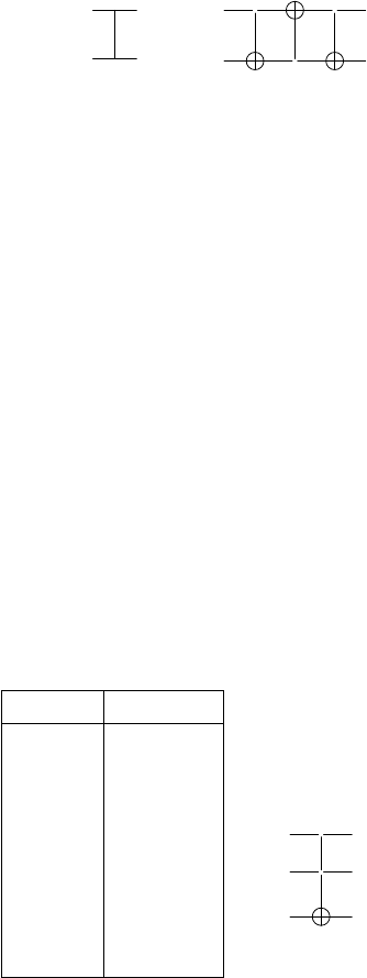
conditional 3-bit gates are in fact universal. The most important for these are:
• gate: T is a doubly controlled NOT gate. Two control bits have to be
set to 1 for NOT to act on the third bit. Else nothing changes. The truth
table and circuit representation are as follows:
x y z x
0
y
0
z
0
0 0 0 0 0 0
0 0 1 0 0 1
0 1 0 0 1 0
0 1 1 0 1 1
1 0 0 1 0 0
1 0 1 1 0 1
1 1 0 1 1 1
1 1 1 1 1 0
x
•
x
y
•
y
z
z ⊕xy
(6.19)
114 Introduction to Quantum Physics and Information Processing
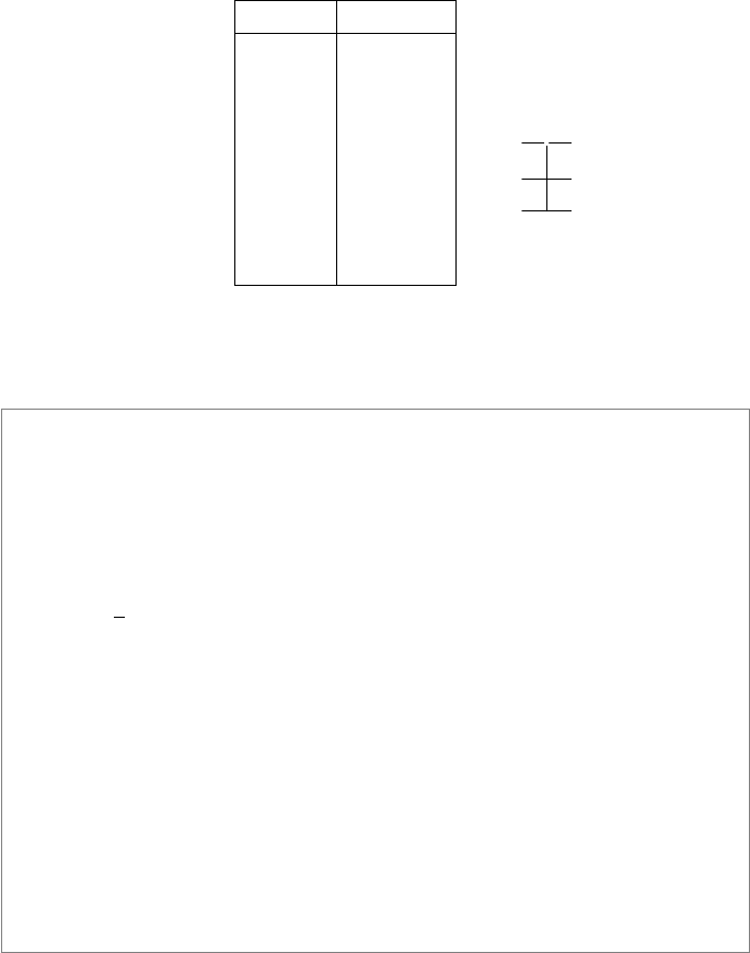
• Fredkin gate: F is a controlled swap gate. If the control bit is set, then
the other two bits are swapped.
x y z x
0
y
0
z
0
0 0 0 0 0 0
0 0 1 0 0 1
0 1 0 0 1 0
0 1 1 0 1 1
1 0 0 1 0 0
1 0 1 1 1 0
1 1 0 1 0 1
1 1 1 1 1 1
x
•
x
y
×
xy + ¯xz
z
×
xz + ¯xy
(6.20)
Exercise 6.4. Find out the matrix representations for the T and F gates.
Box 6.1: Billiard Ball Reversible Computer
The Fredkin gate has an interesting origin. It arose out of a mechanical
model for reversible computation based on elastic collisions of a system of
billiard balls and reflecting walls in a frictionless environment, proposed in
1982 by Fredkin and Toffoli [35]. A ball appearing at a port represents a
logical 1 at that port, while the absence of a ball at a port represents a logical
0. The movement is restricted to a grid with unit distance, and the balls have
radius 1/
√
2 to capture discrete time steps. Inside the “computer”, a billiard
ball shot forward in a direction 45
◦
up could collide with another ball or with
horizontal reflecting walls, so that it always stays on the grid. At the output
ports one obtains a readout of the process based on which ports are occupied
and which are not. A series of well-placed reflectors would achieve a circuit
built out of Fredkin gates. Since the collisions of the balls with the reflectors
are nearly perfectly elastic, no energy is lost and we have an energy-conserving
implementation of a reversible computation. A further property of the Fredkin
gate, reflected by the billiard ball model, is that it is conservative, that is, the
number of 1’s in the input is preserved in the output. This just translates
into no ball being lost in the computer. Conservativeness is also a concern of
physical implementations of computation.
One way to see how such a 3-bit gate may be universal is to show how
to implement the (irreversible) universal set {AND, NOT, OR, COPY} using
only this gate.
Computation Models and Computational Complexity 115
Example 6.3.1. The universality of the Fredkin gate can be demonstrated by
using it to implement the four universal logic gates:
AND OR NOT and COPY
x
•
x
y
×
0
×
xy
x
•
x
y
×
x ∧ y
1
×
x
•
x
0
×
x
1
×
¯x
For the output of the OR gate, we have used
x + ¯xy = x + (1 − x)y = x + y − xy = x ∧ y.
Also note how the required output appears at one port and the other ports
are ignored. This is a common feature in implementing irreversible gates em-
bedded in bigger, reversible ones.
Exercise 6.5. Show how {AND, NOT, OR, COPY} can be implemented by Tof-
foli gates alone.
Thus, these classical universal gates can implement any function, provided
some of the inputs are chosen to take fixed values, and some of the outputs
are ignored, as in Figure 6.5.
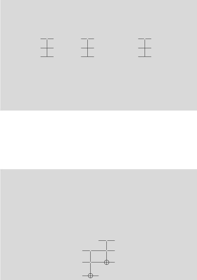
Example 6.3.2. A reversible half-adder:
Let’s see how to build a simple reversible circuit, for example a 1-bit adder,
using Toffoli gates alone. The function we need must calculate the sum which
is addition mod 2 of the inputs: s = x ⊕ y, and the carry which is the AND
of the inputs: c = xy.
f
add
(x, y . . .) = (x, y, x ⊕ y, xy).
Check that the following circuit does what we need:
1
•
x
• •
x
y
•
s = x ⊕ y
0
c = xy
Exercise 6.6. Construct a half-adder using Fredkin gates alone.
Leave a Reply