
Classical computation using binary variables works on Boolean logic, and
implementation of basic logical operations are done through logic gates that
are well known. We will revise their behaviour and notation and express their
action as matrix operators.
We will think of a computation as effected by a circuit evaluating some
Boolean function whose input is a binary n-bit number, and output may be
an m-bit number:
f : {0, 1}
n
7→ {0, 1}
m
. (6.1)
As a circuit this is represented in the following diagram:
f
n m
The computation is effected by a combination of logic gates. One can
represent an n-bit input to a gate as a 2
n
× 1 column vector and the output
as a 2
m
× 1 column vector. The action of the gate is then represented by a
2
m
× 2
n
matrix.
A single classical bit takes two mutually exclusive logical values, that can
be written as the two basis vectors:
0 ≡
“
1
0
#
, 1 ≡
“
0
1
#
. (6.2)
The logical operation NOT takes a bit and gives its complement: x → ¯x. We
can algebraically represent this operation of negation as x → 1 −x. Physically
it ca nbe implemented by the NOT gate, which flips the value of the input
bit, as specified by the truth table and operation
Input Output
0 1
1 0
,
“
1
0
#
→
“
0
1
#
,
“
0
1
#
→
“
1
0
#
. (6.3)
This action can be executed by operation of the following 2 × 2 matrix on
either of the bit values:
NOT =
“
0 1
1 0
#
. (6.4)
There are more operations possible on two and higher bits. The two-bit num-
bers are given by 4 column vectors
00 ≡
1
0
0
0
, 01 ≡
0
1
0
0
, 10 ≡
0
0
1
0
, 11 ≡
0
0
0
1
. (6.5)
A very useful two-bit operation is the AND, which gives an output 1 if an only
if both input bits are 1. As a gate, it is given by the truth table and operation
Input Output
00 0
01 0
10 0
11 1
,
1
0
0
0
→
“
1
0
#
,
0
1
0
0
→
“
1
0
#
,
0
0
1
0
→
“
1
0
#
,
0
0
0
1
→
“
0
1
#
.(6.6)
To represent this operation we need a 2
2
× 2 matrix:
AND =
“
1 1 1 0
0 0 0 1
#
(6.7)
Algebraically, AND can be executed by (x, y) → x ∧ y = xy.
Various other logical operations on two bits are possible, such as the OR,
the complements of AND and OR called NAND and NOR respectively, and
the exclusive-OR or XOR. These along with their symbols and algebraic equiv-
alents are listed in Table 6.1.
Exercise 6.2. Find the matrix representations of the OR and XOR gates.
In classical computations, we often assume that we work on copies of a
Computation Models and Computational Complexity 107
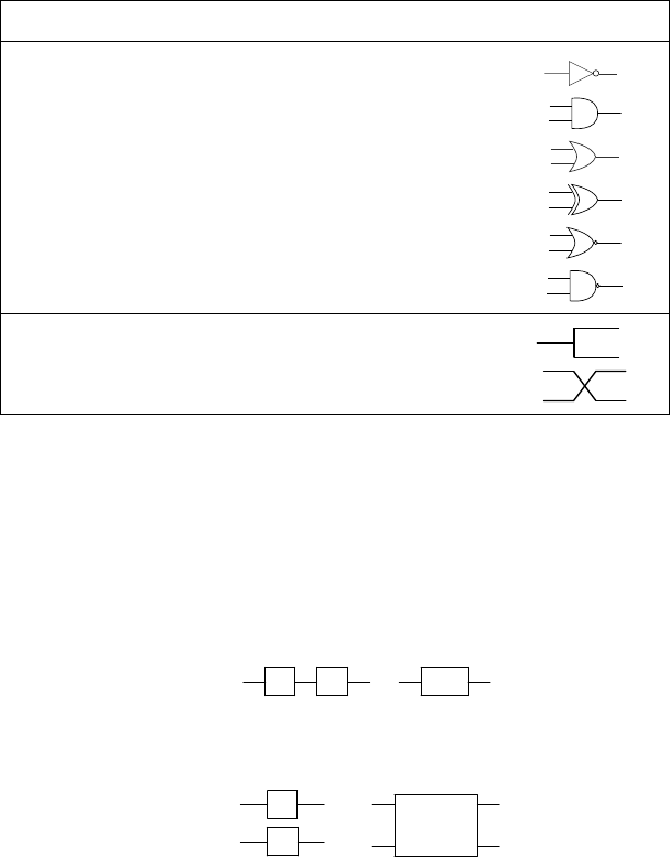
TABLE 6.1: Basic classical gates and their symbols.
Gate Logical Symbol Arithmetic Equivalent Circuit Symbol
NOT: ¯x 1 − x
AND: x
1
∧ x
2
x
1
x
2
OR: x
1
∨ x
2
x
1
+ x
2
− x
1
x
2
XOR: x
1
⊕ x
2
x
1
+ x
2
− 2x
1
x
2
NOR: x
1
↓ x
2
1 − x
1
− x
2
+ x
1
x
2
NAND: x
1
↑ x
2
1 − x
1
x
2
COPY: (fanout) x −→ x, x
SWAP: (crossover) x
1
, x
2
−→ x
2
, x
1
certain input bit, and sometimes inputs are switched. These are included ex-
plicitly among the logic gates, as actions we need to perform though we may
ignore them at times. This becomes especially important when we map clas-
sical functions to quantum ones, because in manipulating qubits, copy can no
longer be implemented, and swap is non-trivial.
We can concatenate gates in series to obtain an effective action by multi-
plying the matrices representing the gates:
A B
≡
BA
.
Further, gates could act in parallel in which case the effective action is
obtained by taking the tensor product of the corresponding matrices.
A
≡
B
A ⊗ B
In general, the evaluation of a function can be converted to an algorithm
involving logic gates acting on the input bits, and a corresponding circuit can
be constructed. Now an n → m function is equivalent to evaluating each of
the m outputs as a {0, 1}
n
→ {0, 1} function. We can therefore restrict our
attention to n → 1 functions. Note that for a given n there are 2
2
n
such
distinct functions.
Now we show that any such function can be evaluated using a small subset
of the above logic gates: a set of universal gates.
Leave a Reply