The Loadbearing Wall
Until the late 19th century, nearly all large buildings were built with loadbearing exterior walls. These walls supported a substantial portion of the floor and roof loads of the building, as well as separating the indoor environment from the outdoors. In noncombustible buildings, these walls were built of brick or stone masonry. Functionally, such walls had several inherent limitations. They were poor thermal insulators, and they were heavy, requiring large foundations and limiting their height to a few stories.
The loadbearing wall has been brought up to date with higher-strength masonry and concrete; components such as thermal insulating materials, cavities, flashings, air barriers, and vapor retarders have been added to make the wall more resistant to the passage of water, air, and heat; and the addition of steel reinforcing has allowed the wall to become thinner, lighter, and better able to resist wind and seismic loads. Loadbearing masonry and concrete exterior walls are often attractive and economical for low- and medium-rise buildings. High-rise residential towers with exterior loadbearing masonry walls also continue to be built, especially in Asia. These types of construction are illustrated and discussed in more detail in Chapters 8, 10, and 14.
The Curtain Wall
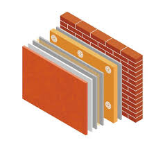
The first steel-framed skyscrapers, built in the late 19th century, introduced the concept of the curtain wall, an exterior wall supported at each story by the frame. The name “curtain wall” derives from the idea that the wall is thin and “hangs” like a curtain on the structural frame. (Most curtain wall panels do not actually hang in tension from the frame but are supported from the bottom at each floor level.) The earliest curtain walls were constructed of masonry (Figure 19.2). The principal advantage of the curtain wall is that, because it bears no vertical load, it can be thin and lightweight regardless of the height of the building, compared to a masonry loadbearing wall, which may become prohibitively thick and weighty at the base of a very tall building.
Curtain walls may be constructed of any noncombustible material that is suitable for exposure to the weather. They may be either constructed in place or prefabricated. In the next chapter, we will examine curtain walls that are made of masonry and concrete. In Chapter 21, we will look at curtain walls that are made of metal and glass. In both chapters, we will see that some types of walls are constructed in place and others are prefabricated, but all are supported by the frame of the building.
BUILDING ENCLOSURE ESSENTIALS: AIR BARRIER
Air Leakage
Air can move through a building assembly wherever air pressure differences exist between one side of the assembly and the other. Such pressure differences can be created by wind forces acting on the external surfaces of a building, by stack effect (the tendency of tall buildings to act somewhat like chimneys, drawing air in at either the top or bottom and expelling it at the other end), and by building mechanical equipment such as exhaust fans and air handling systems (Figure A).
When outside air infiltrates a building through exterior walls and roofs, it increases building energy consumption. A 2005 study by the U.S. National Institute of Standards and Technology estimated that air infiltration can account for as much as 40 percent of a building’s heating and cooling costs. Outside air infiltration also introduces unfiltered air pollutants and unconditioned air into the building’s interior, where it can compromise indoor air quality and reduce occupant comfort. Air leakage transports water vapor into insulated walls and roofs, increasing the risk of condensation and moisture damage to building components. When air leaks between spaces within a building, it can disrupt pressure differentials maintained by HVAC systems for the purpose of controlling the spread of odors or contaminants between separately zoned parts of a building. For example, unpleasant cooking odors can be drawn from one apartment building living unit to another, car exhaust or gas fumes from a parking garage can infiltrate adjacent occupied areas, dust particles can be carried into a laboratory clean room, or bacteria can be introduced into a hospital operating suite.
Air Barriers
Air barrier materials act to reduce air leakage through a building assembly. Examples of air barrier materials include building wrap, gypsum wallboard, polyethylene sheet plastic, rigid foam insulation, liquid-applied membranes of various formulations, caulking, sealants, gaskets, tapes, and more. To function as an air barrier, a material must be resistant to the passage of air; it must have sufficient strength and rigidity to withstand the air pressure differentials that act upon it; where it spans movement joints, it must be sufficiently resilient to accommodate movement without failure; and it must be durable enough to perform its function throughout the life of the building.
The greater a material’s resistance to the passage of air, the lower its air permeance and the better its performance as an air barrier. Air permeance is measured according to ASTM E2178 and is expressed as cubic feet of air per minute per square foot of area at 1.57 pounds per square foot (or 0.3 inch of water) of air pressure, or, in metric units, as liters per second per square meter of area at 75 Pascals of air pressure. An air permeance of 1 cfm/[email protected] psf is equal to approximately 5 L/s-m2@75 Pa. The most commonly cited standard for air barrier materials is an air permeance not greater than 0.004 cfm/[email protected] psf or 0.02 L/s-m2@75 Pa (Figure B).
An air barrier material must be able to resist air pressure, acting either inward or outward across the building assembly, without damage or excessive deflection. Flexible sheet materials such as building wraps, plastic sheets, roofing membranes, and flexible flashings are especially vulnerable. If not properly supported or adequately fastened, these materials can tear, stretch, or pull loose and become ineffective as air barriers. Damage caused by air pressures can also lead to the failure of materials to perform other important functions, such as keeping liquid water out of the building or resisting the diffusion of water vapor. If an air barrier material remains intact but deflects excessively under alternating cycles of positive and negative air pressure, it can pump air in and out of a building assembly, reducing the effectiveness of insulation and increasing the risk of water vapor transport into the assembly. Air barrier materials must also be able to accommodate the normal thermal and structural movements that occur within building systems without undue wear or failure.
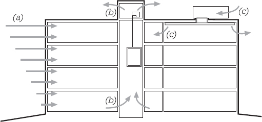
Figure A Air pressure differences in a building can be caused by (a) wind, (b) the stack effect, such as within an elevator shaft, and (c) building mechanical systems.
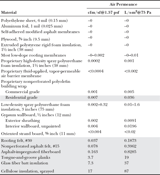
Figure B Air permeance of common building materials. Shaded rows indicate materials exceeding recommended air permeance for air barrier materials.
Air Barrier Systems
To limit air leakage into and out of a building, its conditioned space must be completely surrounded by air barrier materials, creating an uninterrupted air barrier system of surfaces, membranes, manufactured components, gap fillers, and joint sealers that can effectively resist air pressure differentials acting across this boundary. Careful attention to detail during design and construction is required to achieve this goal. All potential discontinuities in the air barrier system—gaps between panels, laps in sheet materials, transitions between dissimilar substrates, fastener penetrations, movement joints, penetrations for structure or services, installation space around window and doors frames, junctions between foundation, wall, and roof assemblies, gaps between operable doors and windows and their frames, and so on—must be made airtight by the use of tapes, sealants, caulks, flashing, gaskets, and other materials that can themselves meet the air permeance limits and structural requirements of an air barrier material. Due to the significant air pressure differentials acting across the air barrier system, even small gaps can allow large volumes of air and water vapor to pass through the building enclosure and must therefore be minimized to the greatest extent possible.
Air permeance standards for the performance of assembled air barrier materials are less stringent than those for individual materials, reflecting the reality that flawless, continuous sealing between materials and components is never possible. Recommendations for the maximum air permeance of air barrier assemblies, that is, collections of materials responsible for the air barrier performance of a complete wall, roof, or floor system, are in the range of 0.01 to 0.04 cfm/[email protected] psf (0.05 to 0.2 L/s-m2@75 Pa). Acceptable air leakage rates for whole building air barrier systems, reflecting the combined performance of a building’s connected air barrier assemblies, fenestration, and other enclosing elements, can be expected to be even greater.
Air Barrier Location
Air barrier materials can be located anywhere in an assembly as long as they form an interconnected airtight system. At the inside surface of the building enclosure, the Airtight Drywall Approach and Simple Caulk and Seal are air barrier systems consisting of gypsum wallboard combined with caulks, sealants, and gaskets to seal leakage paths around wallboard penetrations and between underlying framing members (Figure 7.22). These systems are relatively easy and inexpensive to install, making them especially popular for residential construction. They are less favored for commercial building types where frequent changes to interior partitions, finishes, and wiring make it unlikely that the continuity of a system depending on the careful detailing of these elements will be maintained over the life of the building.
Plastic sheeting, frequently used as a vapor retarder behind gypsum wallboard, also has low air permeance and can act as an air barrier. However, difficulty in sealing plastic sheet seams and penetrations, as well as a tendency for the plastic to stretch and deflect between supporting framing, limit this material’s suitability in air barrier systems, especially for taller buildings or wherever else high air pressure differentials are expected.
Toward the middle of a building enclosure assembly, foam insulation can be sprayed into the space between studs, joists, and rafters, acting as part of an air barrier system in combination with caulks or sealants to seal leakage paths around framing members. Air barrier materials located close to the interior side of the building enclosure or within framing cavities also benefit from being protected from the exterior elements.
Toward the outside of the building enclosure, air barrier materials are frequently installed over sheathing in framed construction or on the exterior face of masonry or concrete backup walls. Building wraps, plywood or gypsum board sheathing panels, and fluid-applied or fully adhered sheet membranes may all be used in combination with various sealing and taping materials. In this location, air barrier materials are easy to install, with a minimum of complex intersections. Where penetrations occur for the anchoring of cladding or sheathing, they are usually easily sealed to ensure airtightness (Figure 20.1b).
Where air barriers fall to the exterior side of the building insulation, they can also protect against wind washing, in which exterior air currents within the assembly reduce insulation effectiveness. However, materials close to the exterior side of a building assembly must also be especially durable and able to perform satisfactorily while exposed to the effects of penetrating rainfall and large temperature fluctuations over the life of the building. In taller buildings, systems consisting of liquid-applied or sheet membranes that are fully adhered to rigid substrates are superior to flexible sheets such as building wrap. As noted earlier, loose sheet materials can be compromised by tearing or excessive deflection. Exterior-side air barrier materials also frequently play an important role in keeping liquid water out of the building enclosure, forming water-resistant drainage surfaces behind the outer cladding.
Unlike vapor retarders, there is no harm in installing multiple air barriers within one assembly. Multiple air barriers can provide the particular advantages of each type of system and can also provide redundancy, lessening the chance of a flaw in one material compromising a building’s overall air leakage performance.
Air Barriers and Water Vapor Control
When air passes through a building assembly, the water vapor in the air is transported through the assembly as well. Where significant air pressure differentials exist between one side of an assembly and the other, the amount of water vapor transported through a building assembly by uncontrolled air leakage can be one or two orders of magnitude greater than that transported by water vapor diffusing directly through building materials. By controlling the flow of warm, moist air toward the cooler side of a building assembly, air barriers can play an important role in protecting against condensation within the assembly.
When designing air barrier systems, the water vapor permeability of the air barrier material must be considered. For example, in a heating-driven climate, an air barrier material located toward the outer, cooler side of an insulated building assembly must be vapor permeable to prevent the trapping of moisture within the assembly. Traditional building paper and breathable building wraps are good choices for use in this application; by contrast, a bituminous membrane, with low vapor permeability, would be a poor choice.
As a general rule, air barrier materials located on the cooler, lower-vapor-pressure side of a building assembly should always be vapor permeable. Conversely, air barriers located on the warmer, higher-vapor-pressure side of an assembly, may consist of materials with low vapor permeance and be designed to function as both an air barrier and a vapor retarder. For more information on vapor retarders and the control of water vapor diffusion in insulated building assemblies, see pages 658–661.
Building Code Air Barrier Requirements
The National Building Code of Canada (2005) sets quantifiable air permeance limits for air barrier materials and requires the control of air leakage with continuous air barrier systems in most buildings. The International Energy Conservation Code (2006) has more limited requirements for controlling air leakage, calling for the sealing of gaps through building envelope assemblies but without setting measurable criteria. At the time of this writing, several U.S. states have adopted more comprehensive air barrier system requirements based on Canada’s model code, and it is likely that requirements for such systems will continue to spread in the United States over the coming years.
Leave a Reply