A reinforced concrete wall at ground level usually rests on a poured concrete strip footing (Figures 14.5–14.7). The footing is formed and poured much like a concrete slab on grade. Its cross-sectional dimensions and its reinforcing, if any, are determined by the structural engineer. A key, a groove that will form a mechanical connection to the wall, is sometimes formed in the top of the footing with strips of wood that are temporarily embedded in the wet concrete. Vertically projecting dowels of steel reinforcing bars are usually installed in the footing before pouring; these will later be overlapped with the vertical bars in the walls to form a strong structural connection. After pouring, the top of the footing is screeded; no further finishing operations are required. The footing is left to cure for at least a day before the wall forms are erected.
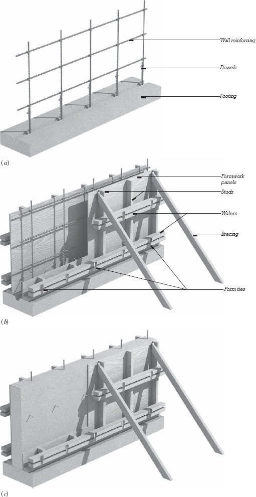
FIGURE 14.5 The process of casting a concrete wall. (a) Vertical reinforcing bars are wired to the dowels that project from the footing, and horizontal bars are wired to the vertical bars. (b) The formwork is erected. Sheets of plywood form the faces of the concrete. They are supported by vertical wood studs. The studs are supported against the pressure of the wet concrete by horizontal walers. The walers are supported by steel rod ties that pass through holes in the plywood to the walers on the other side. The ties also act as spreaders to maintain a spacing between the plywood walls that is equal to the desired thickness of the wall. Diagonal braces keep the whole assembly plumb and straight. (c) After the concrete has been poured, consolidated, and cured, the wedges that secure the walers to the form ties are driven out and the formwork is pulled off the concrete. The projecting ends of the form ties are broken off.
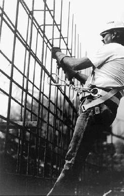
FIGURE 14.6 Protected against falling by a safety harness, a worker stands on the reinforcing bars for a concrete wall to wire another horizontal bar in position. (Photo courtesy of DBI/SALA, Fed Wing, Minnesota)
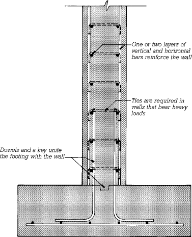
FIGURE 14.7 Section through a reinforced concrete wall, with two layers of horizontal and vertical reinforcing bars for greater strength.
The wall reinforcing, either in one vertical layer of horizontal and vertical bars at the center of the wall or two vertical layers near the faces of the wall, as specified by the structural engineer, is installed next, with the bars wired to one another at the intersections. The vertical bars are overlapped with the corresponding dowels projecting from the footing. L-shaped horizontal bars are installed at wall corners to maintain full structural continuity between the two portions of the wall. If the top of the wall will connect to a concrete floor or another wall, rods are left projecting from the formwork. These will be embedded in the later pour of concrete to form a continuous connection.
Wall forms may be custom built of lumber and plywood for each job, but it is more usual to use standard reusable prefabricated formwork panels. The panels for one side of the form are coated with a form release compound, set on the footing, aligned carefully, and braced. The form ties, which are small-diameter steel rods specially shaped to hold the formwork together under the pressure of the wet concrete, are inserted through holes provided in the formwork panels and secured to the back of the form by devices supplied with the form ties. Both ties and fasteners vary in detail from one manufacturer to another (Figures 14.8 and 14.9). The ties will pass straight through the concrete wall from one side to the other and remain embedded permanently in the wall after it is poured. This may seem like an odd way to hold wall forms together, but the pressures of the wet, heavy concrete on the forms are so large that there is no other economical way of dealing with them.
When the ties are in place and the reinforcing has been inspected, the formwork for the second side of the wall is erected, the walers and braces are added (Figure 14.5), and the forms are inspected to be sure that they are straight, plumb, correctly aligned, and adequately tied and braced. A surveyor’s transit or laser leveling device is used to establish the exact height to which the concrete will be poured, and this height is marked all around the inside of the forms. Pouring may then proceed.
Concrete is brought to the site, test cylinders are made, and a slump test is performed to check for the proper pouring consistency. Concrete is then transported to the top of the wall by a large crane-mounted bucket or by a concrete pump and hose. Workers standing on planks at the tops of the forms deposit the concrete in the forms, consolidating it with a vibrator to eliminate air pockets (Figure 14.10). When the form has been filled and consolidated up to the level that was marked inside the formwork, hand floats are used to smooth and level the top of the wall. The top of the form is then covered with a plastic sheet or canvas, and the wall is left to cure.
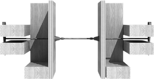
FIGURE 14.8 Detail of a form tie assembly. Two plastic cones just inside the faces of the form maintain the correct wall thickness. Tapered, slotted wedges at the ends transmit force from the tie to the walers. After the forms have been stripped, the cones will be removed from the concrete and the ties snapped off inside the voids left by the cones. The conical holes may be left open, filled with mortar, or plugged with conical plastic plugs.
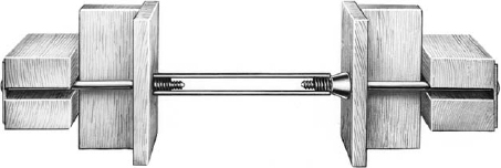
FIGURE 14.9 Detail of a heavy-duty form tie. This assembly is tightened with special screws that engage a helix of heavy wire welded into the tie. The wire components remain in the concrete, but the screws and the plastic cone on the right are removed and reused after stripping. The purpose of the cone is to give a neatly finished hole in the exposed surface of the concrete. (Courtesy of Richmond Screw Anchor Co., Inc., 7214 Burns St., Fort Worth, TX 76118)
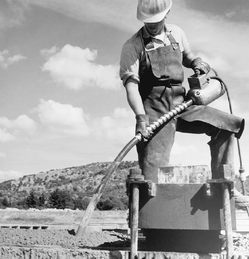
FIGURE 14.10 Consolidating wet concrete after pouring, using a mechanical vibrator immersed in the concrete. (Reprinted with permission of the Portland Cement Association from Design and Control of Concrete Mixtures, 12th edition; Photos: Portland Cement Association, Skokie, IL)
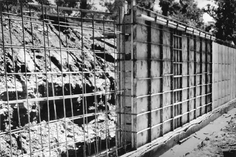
FIGURE 14.11 Three stages in the construction of a reinforced concrete wall on a strip footing. In the foreground, the reinforcing bars have been wired to the dowels that project from the footing, ready for erection of the formwork. In the center, a section of wall has been poured in proprietary steel formwork that is tied through the wall with small steel straps secured by wedges. In the background, the forms have been stripped, and some of the ties have been snapped off. (Reprinted with permission of the Portland Cement Association from Design and Control of Concrete Mixtures, 12th edition; Photos: Portland Cement Association, Skokie, IL)
After a few days of curing, the bracing and walers are taken down, the connectors are removed from the ends of the form ties, and the formwork is stripped from the wall (Figure 14.11). This leaves the wall bristling with projecting ends of form ties. These are twisted off with heavy pliers, and the form tie holes that they leave in the surfaces of the wall are carefully filled with grout. If required, major defects in the wall surface caused by defects in the formwork, inadequate filling of the forms with concrete, or poor consolidation of the concrete can be repaired at this time. The wall is now complete.
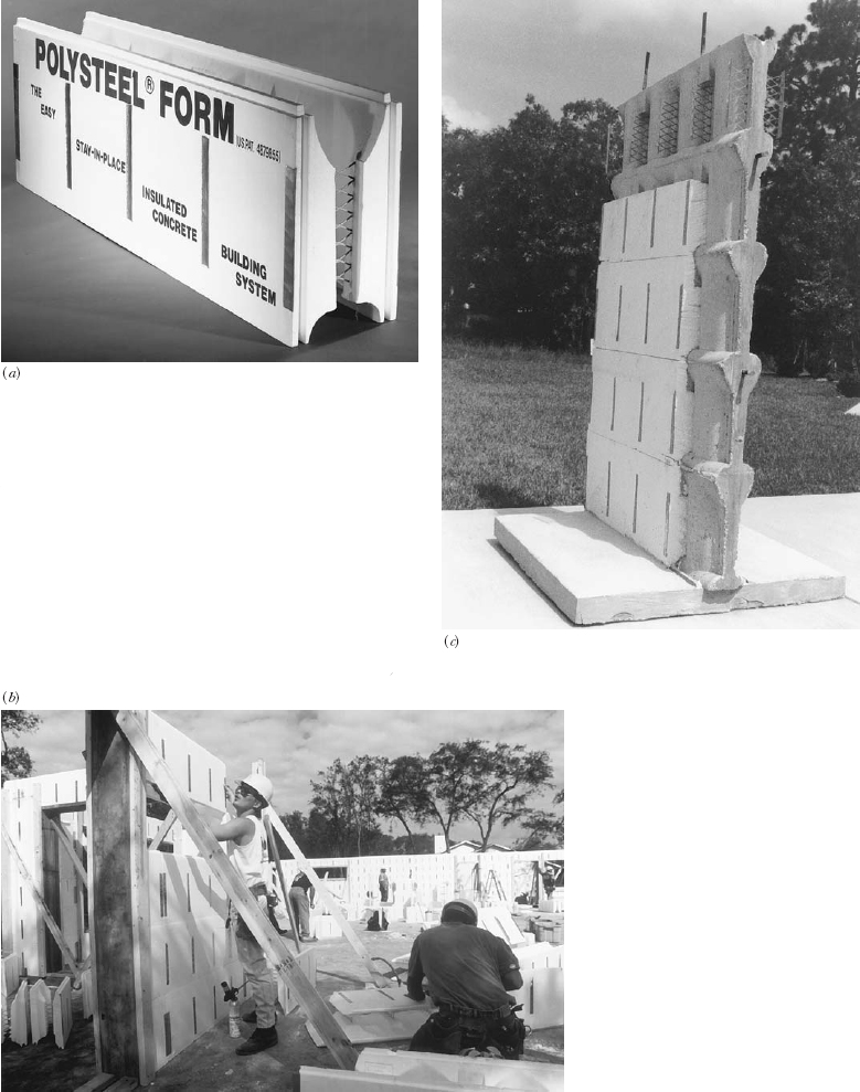
FIGURE 14.12 Forming a concrete wall with insulating concrete forms. (a) The forms are manufactured as interlocking blocks. The inner and outer halves of the blocks are tied together by steel mesh webs that connect to sheet metal strips on the inner and outer surfaces. These strips later serve to receive screws that fasten interior and exterior finish materials to the wall. (b) Workers stack the blocks to form all the exterior walls of a house. Openings for doors and windows are formed with dimension lumber. The worker to the right is cutting a formwork block to length with a hand saw. (c) This sample wall, from which some of the blocks have been removed, shows that the completed wall contains a continuous core of reinforced concrete with thermal insulation inside and out. (Courtesy of American Polysteel Forms)
Insulating Concrete Forms
An alternative way of casting a concrete wall, particularly one that will be an exterior wall of a building, is to use insulating concrete forms (ICFs) that serve both to form the concrete and to remain in place permanently as thermal insulation (Figure 14.12). The forms are manufactured in slightly differing configurations by dozens of companies. The most common form is interlocking hollow blocks of polystyrene foam, but some manufacturers produce planks or panels of foam with plastic ties that join them to make wall forms. Whatever the exact configuration, these systems weigh so little and are so accurately made that they go together almost as easily and quickly as a child’s plastic building blocks. The tops of the blocks are channeled in such a way that horizontal reinforcing bars may be laid in the top of each course and vertical bars may be inserted into the vertical cores. The wall forms must be braced strongly to prevent them from moving during pouring. Concrete is usually deposited in the cores of the foam blocks from the hose of a concrete pump. The full height of a wall cannot be cast in one operation because the pressure of so great a depth of wet concrete would blow out the sides of the fragile blocks. The normal procedure is to deposit the concrete in several “lifts” of limited height, working all the way around the structure with each lift so that by the time the second lift is begun, the first lift has had an hour or two to harden somewhat, relieving the pressure at the bottom of the forms. Interior and exterior finish materials must be applied to the foam plastic faces to protect them from sunlight, mechanical damage, and fire. The thermal insulating value of the finished wall is usually R17 to R22, which is generally sufficient to meet current code requirements.
Leave a Reply