n detailing the exterior wall for water resistance, we work from a secure theoretical base, which can be stated as follows:
In order for water to penetrate a wall, three conditions must be satisfied simultaneously:
1. There must be water present at the outer face of the wall.
2. There must be an opening through which the water can move.
3. There must be a force to move the water through the opening.
If any one of these conditions is not satisfied, the wall will not leak. This suggests three conceptual approaches to making a wall watertight:
1. We can try to keep water completely away from the wall. A very broad roof overhang can keep a one- or two-story wall dry under most conditions. When designing the exterior wall of a taller building, however, we must either shelter each opening with its own small roof—frequently not a realistic option—or else assume that the wall will get wet.
2. We can try to eliminate the openings in a wall. We can build very carefully, sealing every seam in the wall with membranes, sealants, or gaskets, attempting to eliminate every hole and crack.
This approach, which is called the “barrier wall approach,” works fairly well if done well, but it has inherent problems. In a wall made up of sealant-jointed components, the joints are unlikely to be perfect. If a surface is a bit damp, dirty, or oily, sealant may not stick to it. If the worker applying the sealant is insufficiently skilled or has to reach a bit too far to finish a joint, he or she may fail to fill the joint completely. Even if the joints are all made perfectly, building movements can tear the sealant or pull it loose. Because, in this approach, the sealant is on the outside of the building, it is exposed to the full destructive forces of sun, wind, water, and ice and may fail prematurely from weathering. And whatever the cause of sealant failure, because the sealant joint is on the outside face of the wall, it is difficult to reach for inspection and repair. Thus, in practice, the barrier wall approach proves unreliable.
In response to these problems, exterior wall designers often employ a strategy of internal drainage or secondary defense, which accepts the uncertainties of external sealant joints by providing internal drainage channels within the wall to carry away any leakage or condensate and backup sealant joints to the inside of the drainage channels. The ordinary masonry cavity wall facing exemplifies this strategy: The cavity, flashings, and weep holes constitute an internal drainage system for any moisture that finds its way through the facing bricks. Internal drainage systems are an important component of every metal-and-glass curtain wall system on the market, as we will see in Chapter 21.
3. We can try to eliminate or neutralize all the forces that can move water through the wall. These forces are five in number: gravity, momentum, surface tension, capillary action, and air currents (Figure 19.6).
Gravity is a factor in pulling water through a wall only if the wall contains an inclined plane that slopes into, rather than out of, the building. It is usually a simple matter to detail the exterior wall system so that no such inclined planes exist, though sometimes a loose gasket or an errant bead of sealant can create one despite the best efforts of the designer.
The momentum of falling raindrops can drive water through a wall only if there is a suitably oriented slot or hole that goes completely through the wall. Momentum is easily neutralized by applying a cover to each joint in the wall or by designing each joint as a simple labyrinth.
The surface tension of water, which causes it to adhere to the underside of a cladding component, allows water to be drawn into the building. The provision of a simple drip on any underside surface to which water might adhere will eliminate the problem.
Capillary action is the surface tension effect that pulls water through any opening that can be bridged by a water drop. It is the primary force that transports water through the pores of a masonry wall. It can be eliminated as a factor in the entry of water through a wall by making each of the openings in a wall wider than a drop of water can bridge or, if this is not feasible or desirable, by providing a concealed capillary break somewhere inside the opening. In porous materials such as brick, capillary action can be counteracted by applying an invisible coating of silicone-based water repellant, which destroys the adhesive force between water and the walls of the pores in the brick.
The solutions described in the four preceding paragraphs are easy to implement. With relatively straightforward geometric manipulations of the joint, the possibility of leakage caused by four of the five forces that can move water through an opening in a wall can be eliminated. The fifth force, wind currents, is the force most difficult to deal with in designing a wall for watertightness. We can neutralize it by employing pressure-equalized wall design.
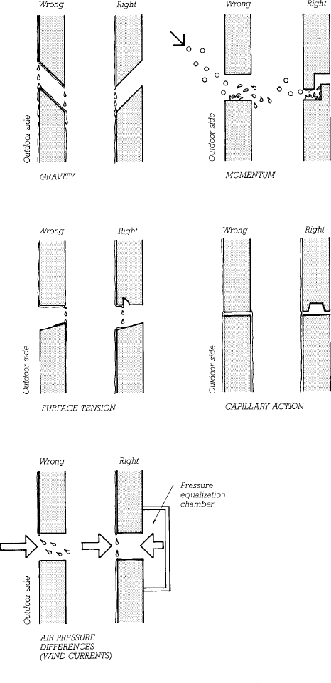
FIGURE 19.6 Five forces that can move water through an opening in a wall, illustrated in cross section with the outdoors to the left. Each pair of drawings shows first a horizontal joint between curtain wall panels in which a force is causing water leakage through the wall, then an alternative design for the joint that neutralizes this force. Leakage caused by gravity is avoided by sloping internal surfaces of joints toward the outside; the slope is called a “wash.” Momentum leakage can be prevented with a simple labyrinth, as shown. A drip and a capillary break are shown here as means for stopping leakage from surface tension and capillary action, which are closely related forces. Air pressure differences between the outside and inside of the joint will result in air currents that can transport water through the joint. This is prevented by closing the area behind the joint with a pressure equalization chamber (PEC), as shown. When wind strikes the face of the building, a slight movement of air through the joint raises the pressure in the PEC until it is equal to the pressure outside the wall, after which all air movement ceases. Each joint in an exterior wall, window, or door must be designed to neutralize all five of these forces.
Rainscreen Cladding and Pressure-Equalized Wall Design
The generic solution to the wind current problem is to allow wind pressure differences between the outside and inside of the exterior wall to neutralize themselves through a concept known as pressure-equalized wall design. This involves the creation of an airtight plane, the air barrier, behind the outer face of the wall. The air barrier is protected from direct exposure to the outdoors by an unsealed, labyrinth-jointed layer known as the rainscreen. Between the rainscreen and the air barrier is a space known as the pressure equalization chamber (PEC).
As wind pressures on the exterior wall build up and fluctuate, small currents of air pass back and forth through each unsealed joint in the rainscreen, just enough to equalize the pressure inside the PEC with the pressure immediately outside it (Figure 19.6). These currents are far too weak to carry water with them. A small flaw in the air barrier, such as a sealant bead that has pulled away from one side of the joint, is unlikely to cause a water leak because the volume of air that can pass through the flaw is still relatively small and is probably insufficient to carry water. By contrast, any flaw, no matter how small, in an external sealant joint without an air barrier behind it will cause a water leak, because the sealant joint itself is wetted (Figure 19.7).
Because wind pressures across the face of a building may vary considerably at any given moment between one area of the face and another, the PEC must be divided into airtight compartments small enough so that volumes of air cannot rush through the joints in higher-pressure areas of the face and flow across the air chamber to lower-pressure areas, carrying water with them as they go. The appropriate size of these chambers may vary considerably, depending on the design of the wall system and the wind forces to which it is exposed. Broadly speaking, PECs are normally no taller than one story or wider than one or two columns bays. In some applications they may be significantly smaller.
The term rainscreen principal originated with the concept of pressure-equalized wall design, and at one time it was used exclusively in reference to pressure-equalized cladding systems. More recently, the term rainscreen cladding has come to be applied more broadly to any cladding system with a system of internal drainage, regardless of the extent of compartmentalization of the drainage space and the degree of pressure equalization that can be achieved. In practice, varying degrees of pressure equalization are achievable, and the line between cladding systems best characterized as simple rainscreens or pressure-equalized walls is often indistinct.
A Pressure-Equalized Wall Design
Figure 19.8 depicts a cladding design that embodies the rainscreen and pressure-equalization principles in very simple form. No surface joint sealants or gaskets are used. The metal rainscreen panels do not touch one another, but are separated by generous gaps that preclude capillary movement of water, provide installation clearances, and allow for expansion and contraction. All four edges of each panel are shaped so as to create labyrinth joints. The forces of surface tension and gravity are counteracted by sloping surfaces and drips.
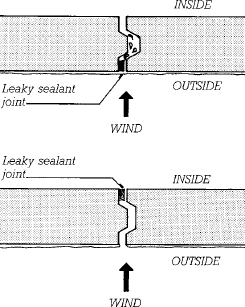
FIGURE 19.7 Leakage through a defective vertical sealant joint between curtain wall panels, shown in plan view. In the upper example, the sealant joint is at the outside face of the panels, where it is wetted during a storm. Even a small current of air passing through the defective joint carries water with it. In the lower example, with the defective sealant located on the inside of the panels where it remains dry, air leakage through the joint is insufficient to transport water through the joint, and no water penetrates.
FIGURE 19.8 The rainscreen in this exemplary cladding system is made up of metal panels, each formed from sheet metal. The design team included Wallace, Floyd Associates, Inc., Bechtel/Parsons Brinckerhoff, Stull and Lee, Inc., Gannett Fleming/URS/TAMS Consultants, and the Massachusetts Highway Department.
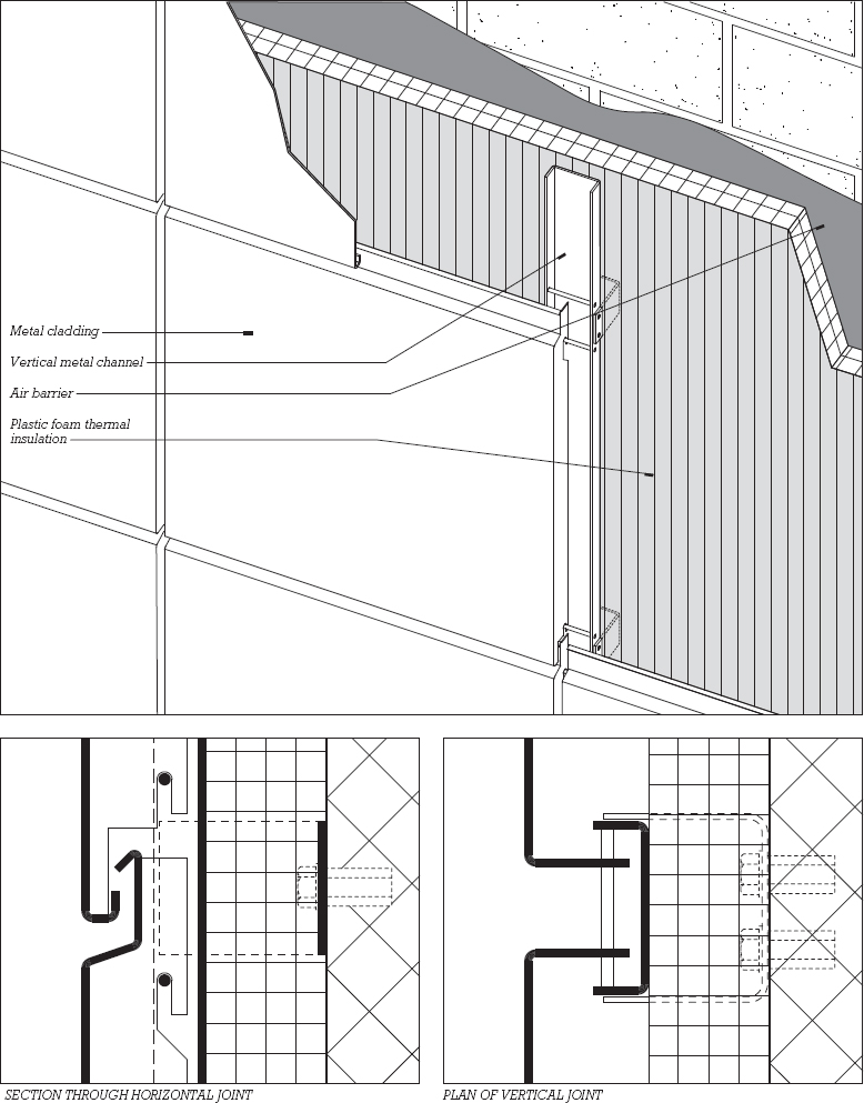
Installation is simple and forgiving of minor lapses in workmanship: Metal U-shaped clips are bolted to the backup wall, which is coated with an airtight mastic to create an air barrier. Rigid insulation panels are adhered to the wall, allowing the clips to project through. Vertical metal channels are bolted to the clips. Finally, the metal panels that make up the rainscreen are simply hung on horizontal rods that are supported by the channels, much as pictures are hung on hooks on a wall. The space between the metal rainscreen panels and the insulation acts as an internal drainage space.
To achieve a pressure-equalized design, horizontal metal angles, not shown, are installed between the channels at one- or two-story intervals. The vertical channels further divide the PEC into narrow compartments. (The spaces between the edges of the panels and the channels are narrow enough to restrict airflow sufficiently to achieve a pressurized design. If more complete compartmentalization is needed, compressible foam rods or gaskets can be installed alongside the channels to create more airtight boundaries at these locations.) When wind drives rain against this wall, small quantities of air flow through the open joints in the rain-screen until the pressure in the PEC equals the pressure outside. These airflows are insufficient in volume or velocity to carry water with them.
Pressure Equalization at Smaller Scale
The principles of rainscreen design and pressure equalization may also be applied on a small scale to guide us in many aspects of exterior detailing of buildings. Figure 19.9 demonstrates how this practice is embodied in the placement of weatherstrip in a window sill detail. In the correct detail, the weatherstrip, whose function is to act as an air barrier, is placed to the inside of the lower rail of the sash. The open joint under the sash rail, which is provided with a capillary break, acts as the PEC. Unless the weatherstrip is grossly defective, water cannot be blown through the joint by air pressure differentials. Notice how the other forces that could transport water through the joint are counteracted: A slope on the sill (called by architects a wash) prevents gravity from pulling water in. The groove in the lower edge of the sash that acts as a capillary break also acts as a drip to counteract surface tension. The L-shaped joint between the sash and the sill acts as a labyrinth to prevent entry by momentum.
In the incorrect detail, the weatherstrip can be wetted by rain. Any minor flaw in the weatherstrip will allow water to be blown through the joint.
Relatively few buildings rely completely on the rainscreen principle and pressure-equalized wall design for watertightness. However, there are very few contemporary cladding systems that do not employ these principles as an important part of their defense against water penetration. Consider again the familiar example of the masonry cavity wall: These principles can be seen in the brick facing wythe acting as a rainscreen, the backup wall as an air barrier, and the cavity, partially pressurized through weep and vent holes, as the PEC. Nevertheless, the surface of the outer masonry veneer is also frequently sealed with compounds to reduce its absorbency (an application of the barrier wall approach), and the cavity is flashed and provided with weep holes so that water that does penetrate the veneer can be safely channeled back to the exterior (an application of internal drainage).
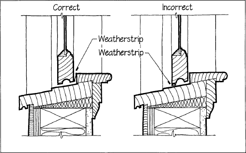
FIGURE 19.9 Applying the rainscreen principle to the detailing of the sill of a double-hung window
Leave a Reply