Glazing Small Lights
Small lights of glass are subjected neither to large wind force stresses nor to large amounts of thermal expansion and contraction. They may be glazed by very simple means (Figure 17.16). In traditional wood sash, the glass is first held in place by small metal glazier’s points and then sealed on the outside with glazing putty, a simple compound of linseed oil and pigment that gradually hardens by oxidation of the oil. Putty must be protected from the weather by subsequent painting, and tends to harden and become brittle with age.
As an alternative to glazing putty, newer latex and silicone caulking compounds that can be applied more quickly and need not be painted may be used for field glazing. Improved, more adhesive, and more elastic putties or glazing compounds are employed for factory-glazed sash as well.
Glazing Large Lights
Large lights of glass (those over 6 square feet or 0.6 m2 in area) require more care in glazing. Wind load stresses on each light of glass are higher, and the glass must span farther between its supporting edges. Any irregularities in the frame of the window may result in distortion of the glass, highly concentrated pressures on small areas of the glass, or glass-to-frame contact, any of which can lead to abrasion or fracture of the glass. In large lights, thermal expansion and contraction can also cause stresses to build up in the glass.
The design objectives for a large-light glazing system are:
1. To support the weight of the glass in such a way that the glass is not subjected to intense or abnormal stress patterns
2. To support the glass against wind pressure and suction
3. To isolate the glass from the effects of structural deflections in the frame of the building and in the smaller framework of mullions that supports the glass
4. To allow for expansion and contraction of both glass and frame without damage to either
5. To avoid contact of the glass with the frame of the window or with any other material that could abrade or stress the glass
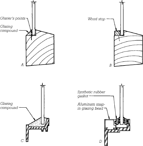
FIGURE 17.16 Alternative methods of single glazing lights of glass. Glass is traditionally mounted in wood sash using glazier’s points and glazing compound (a) or a wood stop nailed to the sash (b). Metal sash was once glazed in the manner shown in (c), but most metal sash is now glazed with snap-in beads and synthetic rubber gaskets, as exemplified in (d).
The weight of the glass is supported in the frame by synthetic rubber setting blocks, normally two per light, located at the quarter points of the bottom edge of the light. For support against wind loads, a specified amount of bite (depth of grip on the edge of the glass) is provided by the supporting mullions. If the bite is too little, the glass may pop out under wind loading; if too much, the glass may not be able to deflect enough under heavy wind loads without being stressed at the edge. The mullions, of course, must be stiff enough to transmit the wind loads from the glass to the frame of the building without deflecting so far as to overstress the glass. The resilient glazing material used to seal the glass-to-mullion joint must be of sufficient dimension and elasticity to allow for any anticipated thermal movement and for possible irregularities in the mullions.
The glazing materials that are most commonly used between the mullions and the glass include wet glazing components and dry glazing components. The wet components are mastic sealants and glazing compounds. The dry components are rubber or elastomeric gaskets. Wet glazing, with good workmanship, is more effective in sealing against penetration of water and air. Dry glazing is faster, easier, and less dependent on workmanship than wet glazing. The two types are often used in combination to utilize the best properties of each.
In the large-light glazing systems shown in Figure 17.17, rubber setting blocks are indicated by the rectangles with X’s in them under the lower edge of the glass. Systems 1, 2, 3, 6, 9, and 10 use preformed solid tape sealant, a thick ribbon of very sticky synthetic that is adhered by pressure to the glass and the mullions. Several different formulations (butyl, polyisobutylene) are usually lumped together under the name polybutene glazing tape. The tape sealant material exerts an extremely strong hold on the glass and stays plastic indefinitely to allow for movement in the glazing system.
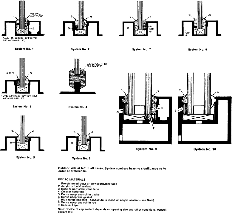
FIGURE 17.17 An assortment of typical large-light glazing details, with the outdoor side to the left. (American Architectural Manufacturers Association Window Selection Guide—1988)

FIGURE 17.18 Inserting the lockstrip into a lockstrip gasket to expand the gasket and seal it against the glass. (Courtesy of Standard Products Company)

FIGURE 17.19 A finished lockstrip gasket glazing installation. (Courtesy of Standard Products Company)
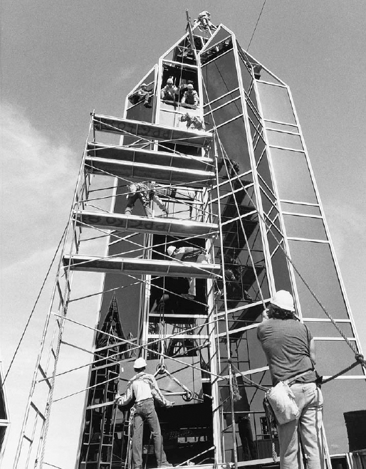
FIGURE 17.20 Glaziers install lights of reflective glass that weigh as much as 125 pounds (57 kg) each in a spire atop an office building. The glass is attached to the hoisting rope by the usual means, suction cups, as seen in front of the worker at the lower left. (John Burgee Architects with Philip Johnson. Photo courtesy of PPG Industries)
Systems 1, 2, 3, 8, and 10 utilize wedge or roll-in gaskets, strips of elastomeric material that are simply pushed into the gap between the glass and the mullion on the interior side to wedge the assembly tightly together and seal against air leakage. Systems 5–10 seal the outside gap with a wet glazing material. System 4 comprises a two-piece lockstrip gasket that is a completely self-contained glazing system. Figures 17.18 and 17.19 show applications of lockstrip gasket glazing.
The properties that solid tape sealants, mastic sealants, and compression gaskets have in common are that they possess the required degree of resiliency, they can be installed in the thickness required to cushion the glass against all expected movements, and they form a watertight seal against both glass and frame. To guard against possible leakage and moisture condensation, however, weep holes should be provided to drain water from the horizontal mullions to the exterior of the window frame, as seen directly below the bottom edge of the glass in Systems 9 and 10 in Figure 17.17.
Advanced Glazing Systems
In their quest to design ever more minimal details for buildings, architects have encouraged the development of systems of glazing that seem, in varying degrees, to defy gravity. In butt-joint glazing, the head and sill of the glass sheets are supported conventionally in metal frames, but vertical mullions are eliminated, the vertical joints between sheets of glass being made by the injection of a colorless silicone sealant. This gives a strong effect of unbroken horizontal bands of glass wrapping continuously around the building (Figures 17.21–17.23).
In structural glazing, the metal mullions lie entirely inside the glass, with the glass adhered to the mullions with structural silicone sealant or, more recently, acrylic foam structural glazing tape. Structural glazing allows the outside skin of the building to be completely flush, unbroken by protruding mullions (Figures 17.24–17.26). Notice in Figure 17.24 that the critical silicone sealant work is done in a factory, not on a construction site. The lights of glass are transported to the site already adhered to the small aluminum channels that will bind them to the mullions. In comparison to structural silicone glazing, acrylic foam structural glazing tape exhibits superior elastic properties, it can be applied more quickly and with less waste, it develops its adhesive bond more quickly, and it produces a cleaner visual appearance.
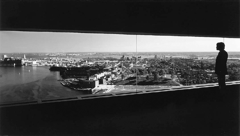
FIGURE 17.21 Mullionless butt-joint glazing uses only a bead of colorless silicone sealant at the vertical joints in the glass. The glass in this example is single glazing ¾ inch (19 mm) thick. (Photo courtesy of LOF Glass, a Libby-Owens-Ford Company)
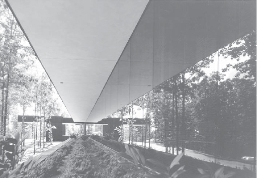
FIGURE 17.22 Another mullionless butt-joint glazing installation, as seen from the outside. (Architects: Neuhaus & Taylor. Photo courtesy of PPG Industries)
Most striking of all are the suspended glazing systems, used primarily for high walls of glass around building lobbies and enclosed grandstands. In the glass mullion system, the tempered glass sheets are suspended from above on special clamps and are stabilized against wind pressure by perpendicular stiffeners, also made of tempered glass, or by systems of tension cables. Where a single sheet of glass spans from the top of the window to the bottom, the glass and stiffeners are joined only by sealant. To create walls that are taller than a single sheet, metal fittings are used to join sheets at the corners and edges (Figures 17.1, 17.10, and 17.27). Stainless steel cables and fittings may be used to support large expanses of glass in roofs (Figures 17.28–17.30 and 17.35). The structure around the perimeter of the opening must be very stiff and strong to resist the pull of the cables that sustain the glass.
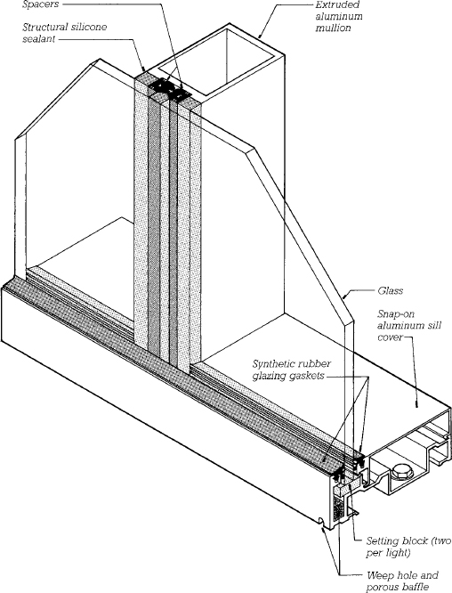
FIGURE 17.23 Horizontal strip windows that need to appear mullionless only from the exterior can be created by adhering the glass to interior mullions with structural silicone sealant. The sill and head are conventionally glazed, using snap-on aluminum covers to hold the interior glazing gaskets. Either single glazing, as shown, or double glazing can be used with this type of system. (Copied by permission from PPG EFG System 401 details. Courtesy of PPG Industries)
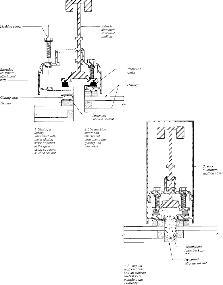
FIGURE 17.24 Steps in the assembly of a mullion for a four-side structural silicone exterior flush glazing system. This system is used to construct multistory glass walls with no metal exposed on the exterior of the building. The adhesive action of structural silicone sealant is the sole means by which the glass is held in place. This system is applicable either to double glazing, as shown, or to single glazing. Notice that the internal complexities of the aluminum components and sealant are completely concealed when the installation is finished. From the inside, one sees only a simple rectangular aluminum mullion, and from the outside, only glass and a thin bead of silicone sealant. (Copied by permission from PPG EFG System 712 details. Courtesy of PPG Industries)
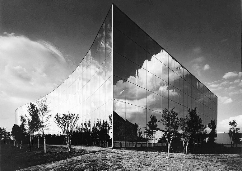
FIGURE 17.25 Reflective glass mounted with a four-side structural silicone glazing system shows no metal on the exterior of this Texas office building, only thin lines of sealant. (Architects: Haldeman, Miller, Bregman & Haman. Photo courtesy of PPG Industries)

FIGURE 17.26 Structural spacer glazing is a patented system of flush glazing that provides a more positive attachment of the double-glazed units to the building. The glass is fastened to the mullion with an aluminum pressure plate that engages a slot in the spacer strip between the sheets of glass. The desiccant required to remove residual moisture from the airspace is mixed with the butyl sealant material in this system.
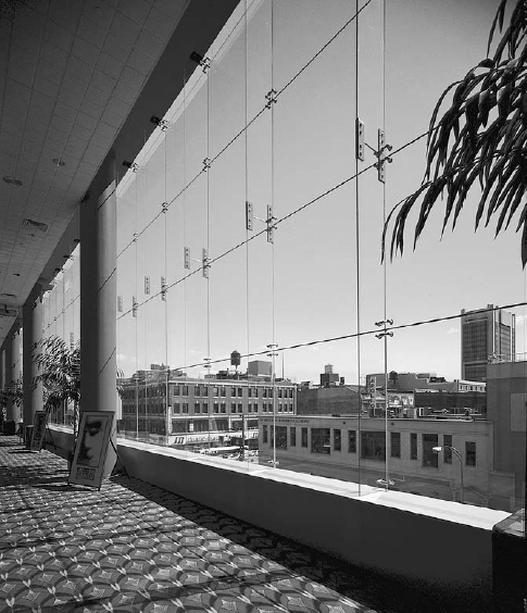
FIGURE 17.27 The low-iron glass in the Magic Johnson Theater in New York City is highly transparent, an effect that is accentuated by suspending the glass from above, using only vertical glass stiffeners to resist wind loads. Stainless steel fittings join the components of the wall. (Photo of Pilkington Planar System courtesy of W&W Glass Systems, Inc.)
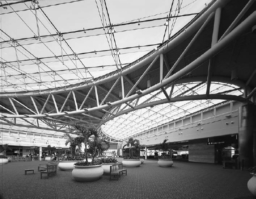
FIGURE 17.28 Airside 2 Terminal at Orlando International Airport, designed by HOK Architects, features large areas of insulating laminated glass units. Laminated glass fins serve as beams to conduct the weight of the roof to vertical stainless steel rods that are supported by a stainless steel cable tensile structure. The downward-hanging cables transmit the weight to the stiff steel pipe trusses around the perimeter, which also resist the inward pull of the cables. The upward-arching cables hold the glass surface down against possible suction forces exerted by wind. Frit was used to diminish reflected glare on glass facing the control tower, and low-e coatings were applied to the insulating glass. (Photo of Pilkington Planar System courtesy of W&W Glass Systems, Inc.)
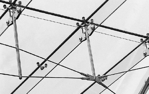
FIGURE 17.29 A detail of the glass roof supports. Notice the four-point and two-point stainless steel spider fittings that attach the glass components to each other and to the metal supporting structure. (Photo of Pilkington Planar System courtesy of W&W Glass Systems, Inc.)
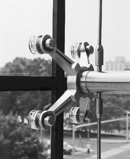
FIGURE 17.30 A close-up view of a four-point spider fitting that holds corners of four individual pieces of insulating glass. Vertical stainless steel rods in adjustable fittings carry the weight of the glass to the structure above. (Photo of Pilkington Planar System courtesy of W&W Glass Systems, Inc.)
Imagine a city iridescent by day, luminous by night, imperishable! Buildings, shimmering fabrics, woven of rich glass; glass all clear or part opaque and part clear, patterned in color or stamped to harmonize with the metal tracery that is to hold it all together, the metal tracery to be, in itself, a thing of delicate beauty consistent with slender steel construction. . . .
Frank Lloyd Wright, in Architectural Record, April 1928
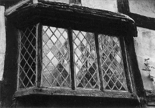
FIGURE 17.31 Leaded diamond-pane windows of handmade rolled glass in an Elizabethan English bay window. (Photo by Edward Allen)
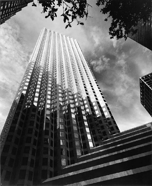
FIGURE 17.32 Discrete windows in an office building. (Architects: Skidmore, Owings and Merrill. Photo courtesy of PPG Industries)

FIGURE 17.33 Limestone and metal mullions for a Gothic church window. (Courtesy Indiana Limestone Institute)
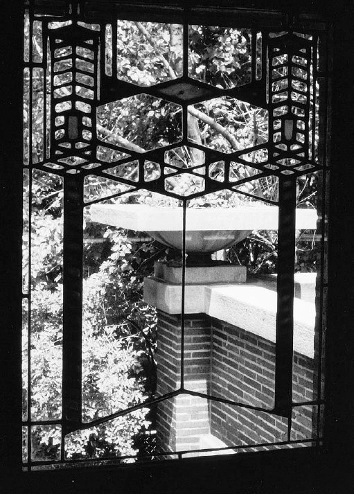
FIGURE 17.34 Leaded stained glass in the Robie House, Chicago, 1906. (Architect: Frank Lloyd Wright. Photo by Edward Allen)
Winter dining rooms and bathrooms should have a southwestern exposure, for the reason that they need the evening light, and also because the setting sun, facing them in all its splendor but with abated heat, lends a gentler warmth to that quarter in the evening. Bedrooms and libraries ought to have an eastern exposure, because their purposes require the morning light . . . . Dining rooms for Spring and Autumn to the east; for when the windows face that quarter, the sun, as he goes on his career from over against them to the west, leaves such rooms at the proper temperature at the time when it is customary to use them.
Marcus Vitruvius Pollio, Roman architect, The Ten Books of Architecture, 1st century B.C.
Leave a Reply