
The development of sitecast concrete construction continues along several lines. The basic materials, concrete and steel, continue to undergo innovations, as described in Chapter 13. The continuing evolution of high-strength, high-stiffness concrete, along with improvements in concrete forming systems and concrete pumping technology, have enabled sitecast concrete construction to remain economically competitive with structural steel for buildings of virtually any type or size. The world’s tallest building at the time of this writing, the Burj Dubai, in Dubai, United Arab Emirates, is being constructed for most of its height as a steel-reinforced sitecast concrete structure.
Formwork generally accounts for more than half the cost of sitecast concrete construction. Efforts to reduce this cost have led to many innovations, including new types of formwork panels that are especially smooth, durable, and easy to clean after they have been stripped. These can be reused dozens of times before they wear out.
FIGURE 14.43 The one-way sitecast concrete framing systems. (a) One-way solid slab with beams and girders. (b) One-way solid slab with slab bands. (c) One-way concrete joist system (rib slab) with joist bands. (d) Wide-module joist system with joist bands. (Drawings by Edward Allen)
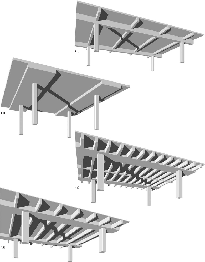
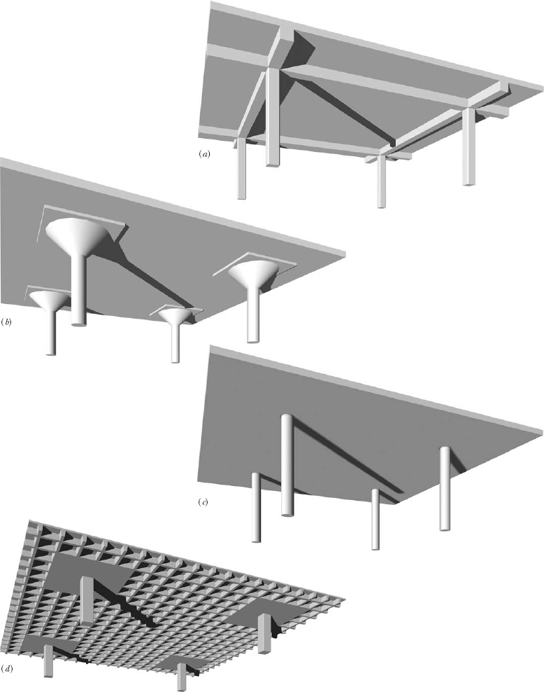
FIGURE 14.44 The two-way sitecast concrete framing systems. (a) Two-way solid slab. (b) Two-way flat slab with drop panels and mushroom capitals. (c) Two-way flat plate. (d) Two-way concrete joist system (waffle slab). (Drawings by Edward Allen)
FOR PRELIMINARY DESIGN OF A SITECAST CONCRETE STRUCTURE
• Estimate the depth of a one-way solid slab at ![]() of its span if it is conventionally reinforced or
of its span if it is conventionally reinforced or ![]() of its span if it is posttensioned. Depths range typically from 4 to 10 inches (100–250 mm).
of its span if it is posttensioned. Depths range typically from 4 to 10 inches (100–250 mm).
• Estimate the total depth of a one-way concrete joist system or wide-module system at ![]() of its span if it is conventionally reinforced or
of its span if it is conventionally reinforced or ![]() of its span if it is posttensioned. For standard sizes of the pans used to form these systems, see Figure 14.23. To arrive at the total depth, a slab thickness of 3 to 4½ inches (75–115 mm) must be added to the depth of the pan that is selected.
of its span if it is posttensioned. For standard sizes of the pans used to form these systems, see Figure 14.23. To arrive at the total depth, a slab thickness of 3 to 4½ inches (75–115 mm) must be added to the depth of the pan that is selected.
• Estimate the depth of concrete beams at ![]() of their span if they are conventionally reinforced or
of their span if they are conventionally reinforced or ![]() of their span if they are posttensioned. For concrete girders, use ratios of
of their span if they are posttensioned. For concrete girders, use ratios of ![]() and
and ![]() , respectively.
, respectively.
• Estimate the depth of two-way flat plates and flat slabs at ![]() of their span if they are conventionally reinforced or
of their span if they are conventionally reinforced or ![]() of their span if they are posttensioned. Typical depths are 5 to 12 inches (125–305 mm). The minimum column size for a flat plate is approximately twice the depth of the slab. The width of a drop panel for a flat slab is usually one-third of the span, and the projection of the drop panel below the slab is about one-half the thickness of the slab.
of their span if they are posttensioned. Typical depths are 5 to 12 inches (125–305 mm). The minimum column size for a flat plate is approximately twice the depth of the slab. The width of a drop panel for a flat slab is usually one-third of the span, and the projection of the drop panel below the slab is about one-half the thickness of the slab.
• Estimate the depth of a waffle slab at ![]() of its span if it is conventionally reinforced or
of its span if it is conventionally reinforced or ![]() of its span if it is posttensioned. For standard sizes of the domes used to form waffle slabs, see Figure 14.35. To arrive at the total depth, a slab thickness of 3 to 4½ inches (75–115 mm) must be added to the depth of the dome that is selected.
of its span if it is posttensioned. For standard sizes of the domes used to form waffle slabs, see Figure 14.35. To arrive at the total depth, a slab thickness of 3 to 4½ inches (75–115 mm) must be added to the depth of the dome that is selected.
• To estimate the size of a concrete column of normal height, add up the total roof and floor area supported by the column. A 12-inch (300-mm) column can support up to about 2000 square feet (190 m2) of area, a 16-inch (400-mm) column 4000 square feet (370 m2), a 20-inch (500-mm) column 6000 square feet (560 m2), a 24-inch (600-mm) column 9000 square feet (840 m2), and a 28-inch (700-mm) column 10,500 square feet (980 m2). These sizes are greatly influenced by the strength of the concrete used and the ratio of reinforcing steel to concrete. Columns are usually round or square.
• To estimate the thickness of a concrete loadbearing wall, add up the total width of floor and roof slabs that contribute load to the wall. An 8-inch (200-mm) wall can support approximately 1200 feet (370 m) of slab, a 10-inch (250-mm) wall 1500 feet (460 m), a 12-inch (300-mm) wall 1700 feet (520 m), and a 16-inch (400-mm) wall 2200 feet (670 m). These thicknesses are greatly influenced by the strength of the concrete used and the ratio of reinforcing steel to concrete.
These approximations are valid only for purposes of preliminary building layout and must not be used to select final member sizes. They apply to the normal range of building occupancies, such as residential, office, commercial, and institutional buildings, and parking garages. For manufacturing and storage buildings, use somewhat larger members.
For more comprehensive information on preliminary selection and layout of a structural system and sizing of structural members, see Edward Allen and Joseph Iano, The Architect’s Studio Companion (4th ed.), Hoboken, John Wiley & Sons, Inc., 2007.
Lift-slab construction, used chiefly with two-way flat plate structures, virtually eliminates formwork. The floor and roof slabs of a building are cast in a stack on the ground. Then hydraulic jacks are used to lift the slabs up the columns to their final elevations, where they are welded in place using special cast-in-place steel slab collars (Figure 14.45).
Ganged forms for wall construction are large units made up of a number of panels that are supported by the same set of walers. These are handled by cranes and are often more economical than conventional small panels that are maneuvered by hand. For floor slabs that are cast in place, flying formwork is fabricated in large sections that are supported on deep metal trusses. The sections are moved from one floor to the next by crane, eliminating much of the labor usually expended on stripping and reerecting formwork (Figure 14.46).
Slip forming is useful for tall-walled structures such as elevator shafts, stairwells, and storage silos. A ring of formwork is pulled steadily upward by jacks supported on the vertical reinforcing bars, while workers add concrete and horizontal reinforcing in a continuous process. Manufacturers of concrete formwork have developed more sophisticated systems of self-climbing formwork that offer many advantages over conventional slip forming (Figures 14.19 and 14.47).
In tilt-up construction (Figure 14.48), a floor slab is cast on the ground and reinforced concrete wall panels are poured over it in a horizontal position. When curing is complete, the panels are tilted up into a vertical orientation and hoisted into position by a crane, then grouted together. The elimination of most of the usual wall formwork results in formwork costs that are typically less than 5 percent of the cost of the overall concrete system, making tilt-up construction often economical for single-story buildings. Although most tilt-up panel construction is for walls no taller than 45 feet (13.7 m), panels for walls approaching heights as great as 100 feet (30 m) are feasible. Tilt-up is probably the most widely used of the innovative concrete construction methods described here.
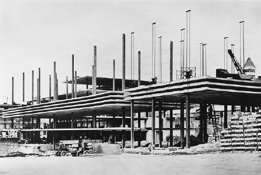
FIGURE 14.45 Lift-slab construction in progress. The paired steel rods silhouetted against the sky to the right are part of the lifting jacks seen at the tops of the columns. In North America, this form of construction is used infrequently, in part due to a history of past construction accidents. (Reprinted with permission of the Portland Cement Association from Design and Control of Concrete Mixtures, 12th edition; Photos: Portland Cement Association, Skokie, IL)
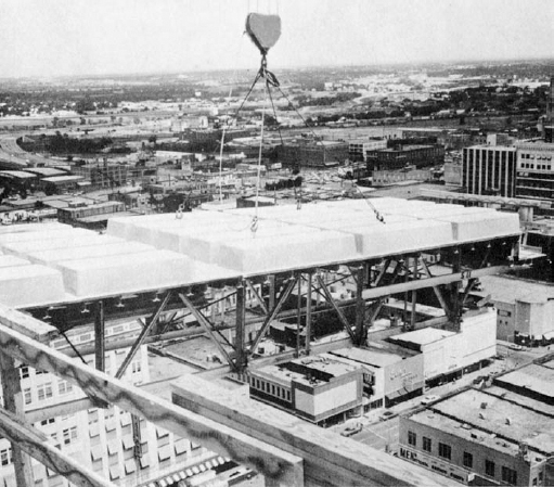
FIGURE 14.46 Flying formwork for a one-way concrete joist system being moved from one floor to the next in preparation for pouring. Stiff metal trusses allow a large area of formwork to be handled by a crane as a single piece. (Courtesy of Molded Fiber Glass Concrete Forms Company)
Shotcrete (pneumatically placed concrete) is sprayed into place from the nozzle of a hose by a stream of compressed air. Because of its very low slump, even walls with vertical sides can be placed with little in the way of conventional formwork, though some kind of solid surface to spray against is required. Shotcrete is used for foundation walls, stabilization of steep slopes, repairing damaged concrete on the faces of beams and columns, seismic retrofits, and the production of free-form structures such as swimming pools and playground structures.
Even greater savings in formwork costs can be realized by casting concrete in reusable molds in a precasting plant, or by combining sitecast concrete with precast forming elements, both of which are the subject of the next chapter.
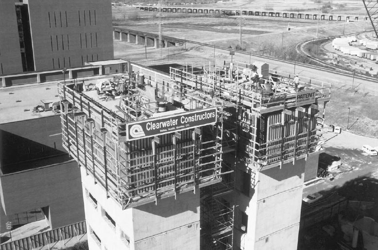
FIGURE 14.47 A proprietary system of self-climbing formwork is being used to form these sitecast concrete elevator shafts for a tall building. The top level is a working surface from which reinforcing bars are handled and the concrete is poured. The outer panels of the formwork are mounted on overhead tracks just beneath the top level. The panels can be rolled back to the outside of the perimeter walkway after each pour, allowing workers to clean the formwork and install the reinforcing for the next pour. The entire two-story apparatus raises itself a story at a time with built-in hydraulic jacks. (Courtesy of Patent Scaffolding Company, Fort Lee, New Jersey)
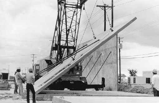
FIGURE 14.48 Tilt-up construction. The exterior wall panels were reinforced and cast flat on the floor slab. Using special lifting rings that were cast into the panels and a lifting harness that exerts equal force on each of the lifting rings, a crane tilts up each panel and places it upright on a strip foundation at the perimeter of the building. Each erected panel is braced temporarily with diagonal steel struts until the roof structure has been completed. (Reprinted with permission of the Portland Cement Association from Design and Control of Concrete Mixtures, 12th edition; Photos: Portland Cement Association, Skokie, IL)
Advances in reinforcing for sitecast concrete, other than the adoption of posttensioning, include a move to higher-strength steels and a trend toward increased prefabrication of reinforcing bars prior to installation in the forms. With developments in welding and fabricating machinery, the concept of welded wire reinforcing is expanding beyond the familiar grid of heavy wire to include complete cages of column reinforcing and entire bays of slab reinforcing. As lighter-weight reinforcing bars based on carbon fiber and aramid fiber come into more common use, other new forms of reinforcing are sure to evolve.
Concrete pumps are becoming the universal means of moving wet concrete from delivery trucks to the point where it is poured. Pumping has many advantages, among them that it can deliver concrete to places that could not possibly be reached by a crane-mounted bucket or even a wheelbarrow. For most projects, concrete is pumped through a flexible hose, but in some very large projects, fixed, rigid pipes are installed for the duration of the construction process to carry the concrete over long distances. The concrete mixture should be designed with the participation of the pumping subcontractor to be sure that it will not clog the line when it is put under pressure by the pump. Concrete can be pumped to astonishing heights and horizontal distances: For the Burj Dubai tower, concrete was pumped more than 1970 vertical feet (600 m).
Leave a Reply