
Two-way concrete framing systems are generally more economical than one-way systems in buildings where the columns can be spaced in bays that are square or nearly square in proportion. A two-way solid slab is a rarely seen system, occasionally used for very heavily loaded industrial floors, in which the slab is supported by a grid of beams running in both directions over the columns. Most two-way floor and roof framing systems, however, even for heavy loadings, are made without beams. The slab is reinforced in such a way that the varying stresses in the different zones of the slab are accommodated within a uniform thickness of concrete. This simplifies formwork construction and reinforcing bar patterns considerably.
The two-way flat slab (Figure 14.28), a system suited to heavily loaded buildings such as storage and industrial buildings, illustrates this concept. The formwork is completely flat except for a thickening of the concrete to resist the high shear forces around the top of each column. Traditionally, this thickening was accomplished with both a funnel-shaped mushroom capital and a square drop panel, but today the capital is usually eliminated to reduce the formwork cost, leaving a drop panel to do the work alone (Figure 14.29). Typical depths for the slab itself range from 6 to 12 inches (150 to 300 mm).
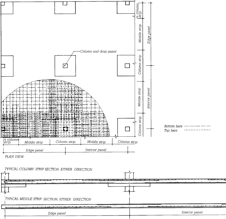
FIGURE 14.28 Plan and larger-scale section of a typical two-way flat slab system. The reinforcing pattern consists of column strips and middle strips, with each strip changing pattern slightly around the perimeter of the building to accommodate the different bending forces that occur in the edge panels. The system shown uses only drop panels without mushroom capitals. The reinforcing in a two-way flat plate system is essentially identical to this example; the only difference is that the flat plate has no drop panels.
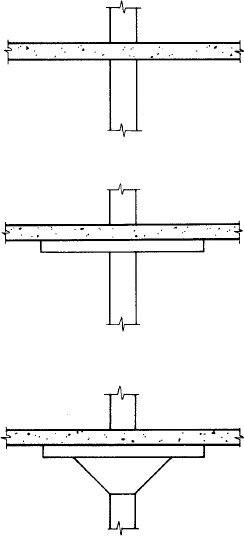
FIGURE 14.29 Column capitals for two-way concrete framing systems. For slabs bearing heavy loads, shear stresses around the column are reduced by means of a mushroom capital and drop panel or a drop panel alone. For lighter loads, no thickening of the slab is required.
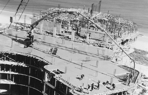
FIGURE 14.30 A two-way flat plate floor of a high-rise apartment building is poured with the aid of a concrete pump at the base of the building. The concrete is delivered up a telescoping tower to a nozzle at the end of an articulated boom. The column dowels in the center of the newly poured area demonstrate the ability of flat plate construction to adapt to irregular patterns and spacings of columns. (Courtesy of Schwing America, Inc.)
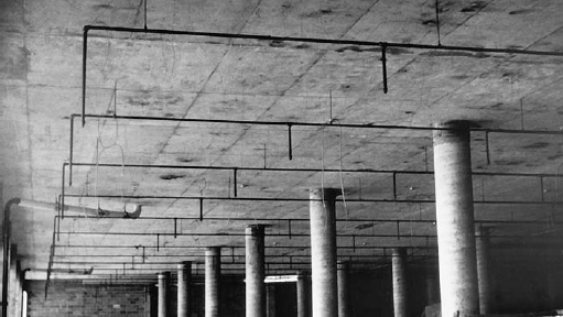
FIGURE 14.31 The underside of a two-way flat plate floor. Pipes have been installed for an automatic sprinkler fire suppression system. (Reprinted with permission of the Portland Cement Association from Design and Control of Concrete Mixtures, 12th edition; Photos: Portland Cement Association, Skokie, IL)
The reinforcing is laid in both directions in half-bay-wide strips of two fundamental types: Column strips are designed to carry the higher bending forces encountered in the zones of the slab that cross the columns. Middle strips have a lighter reinforcing pattern. Shrinkage–temperature steel is not needed in two-way systems because the concrete must be reinforced in both directions to resist bending. The drop panel and capital (if any) have no additional reinforcing beyond that provided by the column strip; the greater thickness of concrete furnishes the required shear resistance.
In more lightly loaded buildings, such as hotels, hospitals, dormitories, and apartment buildings, the slab need not be thickened at all over the columns. This makes the formwork extremely simple and even allows some columns to be moved off the grid a bit if it will facilitate a more efficient floor plan arrangement (Figure 14.30). The completely flat ceilings of this system allow room partitions to be placed anywhere with equal ease. Because there are no beams and girders, only a thin slab, the story heights of the building may be kept to an absolute minimum, which reduces the cost of exterior cladding (Figure 14.31). Typical slab depths for this two-way flat plate system range from 5 to 12 inches (125–305 mm).
The zones along the exterior edges of both the two-way flat slab system and the two-way flat plate system require special attention. To take full advantage of structural continuity, the slabs should be cantilevered beyond the last row of columns a distance equal to about 30 percent of the interior span. If such a cantilever is impossible, additional reinforcing must be added to the slab edges to carry the higher stresses that will result.
Because a two-way flat plate has no drop panel, it requires additional reinforcing bars in the slab at the top of each column to resist the high shear stresses that occur in this region. Alternatively, a proprietary system of vertical steel studs may be installed in the formwork at each column head to act as stirrups and replace a much larger volume of horizontal bars (Figures 14.32 and 14.33).
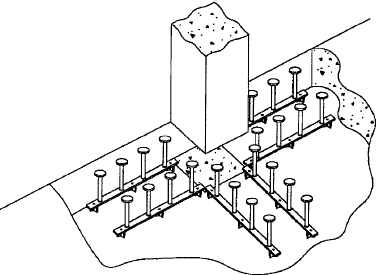
FIGURE 14.32 Shear reinforcement around columns in a two-way flat plate can be simplified by using Studrails®, a proprietary system of steel studs factory welded to horizontal rails. (U.S. and Canada patents Nos. 4406103 and 1085642, respectively. Licensee: Deha, represented by Decon, 105C Atsion Rd., P.O. Box 1575, Medford, NJ 08055-6675 and 35 Devon Road, Bramton, Ontario L6T 5B6)
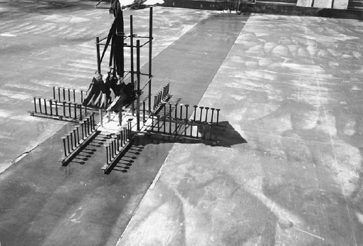
FIGURE 14.33 Studrails nailed to the formwork around column bars, ready for installation of the top and bottom bars for the two-way flat plate. (U.S. and Canada patents Nos. 4406103 and 1085642, respectively. Licensee: Deha, represented by Decon, 105C Atsion Rd., P.O. Box 1575, Medford, NJ 08055-6675 and 35 Devon Road, Bramton, Ontario L6T 5B6)
Two-Way Waffle Slab System
The waffle slab, or two-way concrete joist system (Figure 14.34), is the two-way equivalent of the one-way concrete joist system. Metal or plastic pans called domes are used as formwork to eliminate nonworking concrete from the slab, allowing considerably longer spans than are feasible in the two-way flat plate system. The standard domes form joists 6 inches (152 mm) wide on 36-inch (914-mm) centers, or 5 inches (127 mm) wide on 24-inch (610-mm) centers, in a variety of depths up to 20 inches (500 mm), as shown in Figures 14.35–14.38. Special domes are also available in larger sizes. Solid concrete heads are created around the tops of the columns by leaving the domes out of the formwork in these areas. A head serves the same function as a drop panel in the two-way flat slab system. If a waffle slab cannot be cantilevered at the perimeter of the building, a perimeter beam must be provided. Stripping of the domes is facilitated in many cases by a compressed air fitting at the inside top of each dome. This allows the domes to be popped out of the concrete with the application of a puff of compressed air. The waffle slab system is suited to longer-span, heavily loaded applications, and its coffered underside presents rich architectural opportunities as an exposed ceiling (Figure 14.39). However, the complexity of waffle slab formwork typically renders this system less economical than other systems with comparable span and load-carrying capability, such as one-way joist.
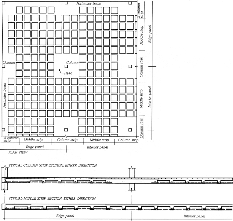
FIGURE 14.34 Plan and larger-scale section of a typical two-way concrete joist system, also known as a waffle slab. No reinforcing is shown on the plan drawing for the sake of clarity, and the section does not show the welded wire fabric that is spread over the entire form before pouring.
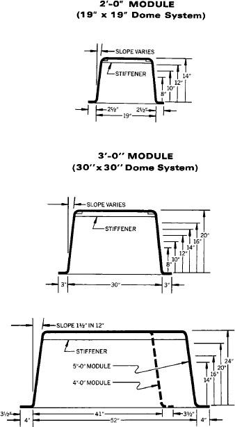
FIGURE 14.35 Standard steel dome forms for two-way concrete joist construction. A 2½-foot (760-mm) module, utilizing forms 24 inches (610 mm) square, is also available from some manufacturers. (One inch equals 25.4 mm.) (Courtesy of the Ceco Corporation, Oakbrook Terrace, Illinois)
FIGURE 14.36 Steel domes being placed on a temporary plywood deck to form a two-way concrete joist floor. Pans are omitted around columns to form solid concrete heads. (Courtesy of the Ceco Corporation, Oakbrook Terrace, Illinois)
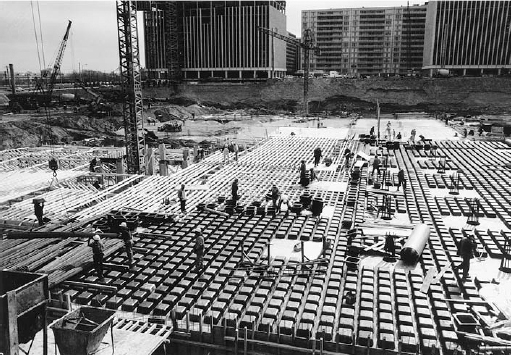
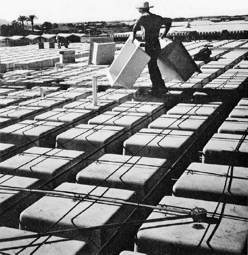
FIGURE 14.37 Plastic dome formwork being assembled for a two-way concrete joist floor. Notice the electrical conduit and junction box in the foreground, ready to be embedded in the slab. (Courtesy of Molded Fiber Glass Concrete Forms Company)
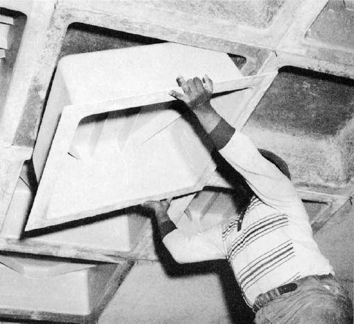
FIGURE 14.38 Stripping plastic domes after removal of the temporary plywood deck. (Courtesy of Molded Fiber Glass Concrete Forms Company)

FIGURE 14.39 The underside of a two-way concrete joist floor. Notice how the joists are cantilevered beyond the column line for maximum structural effi
Leave a Reply