In active systems, water or a heat transfer fluid is pumped through the collectors. These are usually more expensive and a little less efficient than passive systems, particularly if antifreeze measures are required. Additionally, active systems are more difficult to retrofit in houses, especially where there is no basement, because a space is required for the additional equipment, such as the hot water cylinder. Five types of systems belong in this category: direct circulation systems, indirect water-heating systems, air systems, heat pump systems, and pool heating systems. Before giving the details of these systems, the optimum flow rate is examined.
High flow rates have been used in pumped circulation solar water heaters to improve the heat removal factor, FR, and thus maximize the collector efficiency. If the complete system performance is considered, however, rather than the collector as an isolated element of the system, it is found that the solar fraction can be increased if a low flow rate through the collector and a thermally stratified tank are used. Stratification can also be promoted by the use of flow diffusers in the tank and collector loop heat exchangers; for maximum effect, however, it is necessary to combine these features with a low flow rate.
The use of a low flow influences both the system initial capital cost and energy savings. The initial capital cost is affected because the system requires a low-power pump; piping to the collectors can be of smaller diameter (hence less expensive and easier to install), and the smaller tubes require lower thickness and lower-cost thermal insulation because the insulation R value depends on the ratio of outer to inner diameter of the insulation. Additionally, low-flow systems can use very small-diameter collector loop piping, and as a result, flexible annealed copper tubes can be used, which are much easier to install. In this case, the flexible pipe can be hand-bent to change the direction without the need for sharp bends, which lead to higher pressure drop.
According to Duff (1996), the flow in the collector loop should be in the range of 0.2–0.4 l/min m2 of collector aperture area. The effect of low flow rate is examined in Chapter 4, Section 4.1.1. In effect, the penalty for low flow rate is a reduction in collector efficiency due to higher collector temperature rise for a given inlet temperature. For example, for a reduction from 0.9 l/min m2 to 0.3 l/min m2, the efficiency is reduced by about 6%; however, the reduction of the inlet temperature to the collectors because of the improved stratification in the tank more than compensates for the loss of collector efficiency. The pumps required for most of the active systems are low static head centrifugal (also called circulators), which for small domestic applications use 30–50 W of electrical power to work.
5.2.1 Direct circulation systems
A schematic diagram of a direct circulation system is shown in Figure 5.9. In this system, a pump is used to circulate potable water from storage to the collectors when there is enough available solar energy to increase its temperature and then return the heated water to the storage tank until it is needed. The pump is controlled from a differential thermostat that measures and compares the temperature at the collector outlet and the storage tank and operates the pump whenever a certain temperature difference exists. More details are given in Section 5.5.
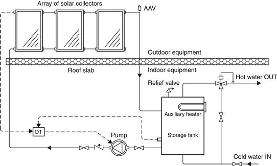
FIGURE 5.9 Direct circulation system.
Because a pump is used to circulate the water, the collectors can be mounted either above or below the storage tank. Direct circulation systems often use a single storage tank equipped with an auxiliary water heater, but two-tank storage systems can also be used. An important feature of this configuration is the spring-loaded check valve, which is used to prevent reverse thermosiphon circulation energy losses when the pump is not running.
Direct circulation systems can be used with water supplied from a cold-water storage tank or connected directly to city water mains. Pressure-reducing valves and pressure relief valves are required, however, when the city water pressure is greater than the working pressure of the collectors. Direct water-heating systems should not be used in areas where the water is extremely hard or acidic, because scale (calcium) deposits may clog or corrode the collectors.
Direct circulation systems can be used in areas where freezing is infrequent. For extreme weather conditions, a freeze protection is usually provided by recirculating warm water from the storage tank. This loses some heat but protects the system. A special thermostat that operates the pump when temperature drops below a certain value is used in this case. Such recirculation freeze protection should be used only for locations where freezing occurs rarely (a few times a year), since stored heat is dumped in the process. A disadvantage of this system occurs in cases when there is power failure, in which case the pump will not work and the system could freeze. In such a case, a dump valve can be installed at the bottom of the collectors to provide additional protection.
For freeze protection, a variation of the direct circulation system, called the drain-down system, is used (shown schematically in Figure 5.10). In this case, potable water is also pumped from storage to the collector array, where it is heated. When a freezing condition or a power failure occurs, the system drains automatically by isolating the collector array and exterior piping from the make-up water supply with the normally closed (NC) valve and draining it using the two normally open (NO) valves, shown in Figure 5.10. It should be noted that the solar collectors and associated piping must be carefully sloped to drain the collector’s exterior piping when circulation stops (see Section 5.4.2). The check valve shown on the top of the collectors in Figure 5.10 is used to allow air to fill the collectors and piping during draining and to escape during a fill-up. The same comments about pressure and scale deposits apply here as for the direct circulation systems.
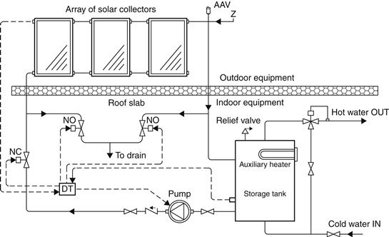
FIGURE 5.10 Drain-down system.
5.2.2 Indirect water-heating systems
A schematic diagram of indirect water-heating systems is shown in Figure 5.11. In this system, the pump also operates with a differential thermostat (see Section 5.5) and a heat transfer fluid is circulated through the closed collector loop to a heat exchanger, where its heat is transferred to the potable water. The most commonly used heat transfer fluids are water–ethylene glycol solutions, although other heat transfer fluids such as silicone oils and refrigerants can be used. When fluids that are non-potable or toxic are used, double-wall heat exchangers should be employed; this can be two heat exchangers in series. The heat exchanger can be located inside the storage tank, around the storage tank (tank mantle), or external to the storage tank (see Section 5.3). It should be noted that the collector loop is closed; therefore, an expansion tank and a pressure relief valve are required. Additional over-temperature protection may be needed to prevent the collector heat-transfer fluid from decomposing or becoming corrosive.
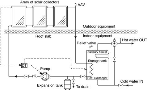
FIGURE 5.11 Indirect water-heating system.
Systems of this type using water–ethylene glycol solutions are preferred in areas subject to extended freezing temperatures, because they offer good freeze protection. These systems are more expensive to construct and operate, since the solution should be checked every year and changed every few years, depending on the solution quality and system temperatures achieved.
Typical collector configurations include the internal heat exchanger shown in Figure 5.11, an external heat exchanger shown in Figure 5.12(a), and a mantle heat exchanger shown in Figure 5.12(b). A general rule to follow is that the storage tank should be between 35 and 70 l/m2 of collector aperture area, while the most widely used size is 50 l/m2. More details on internal heat exchangers are given in Section 5.3.2.
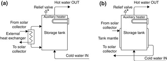
FIGURE 5.12 External and mantle heat exchangers. (a) External heat exchanger. (b) Mantle heat exchanger.
For a freeze protection, a variation of the indirect water-heating system, called the drain-back system, is used. Drain-back systems are generally indirect water-heating systems that circulate water through the closed collector loop to a heat exchanger, where its heat is transferred to potable water. Circulation continues as long as usable energy is available. When the circulation pump stops, the collector fluid drains by gravity to a drain-back tank. If the system is pressurized, the tank also serves as an expansion tank when the system is operating; in this case, it must be protected with temperature and pressure relief valves. In the case of an unpressurized system (Figure 5.13), the tank is open and vented to the atmosphere. The second pipe directed from the collectors to the top of the drain-back tank is to allow air to fill the collectors during a drain-back.
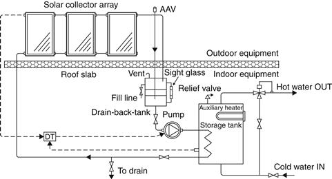
FIGURE 5.13 Drain-back system.
Because the collector loop is isolated from the potable water, no valves are needed to actuate draining and scaling is not a problem; however, the collector array and exterior piping must be adequately sloped to drain completely. Freeze protection is inherent to the drain-back system because the collectors and the piping above the roof are empty whenever the pump is not running. A disadvantage of this system is that a pump with high static lift capability is required in order to fill the collector when the system starts up.
In drain-back systems, there is a possibility that the collectors will be drained during periods of insolation; it is therefore important to select collectors that can withstand prolonged periods of stagnation conditions. Such a case can happen when there is no load and the storage tank reaches a temperature that would not allow the differential thermostat to switch on the solar pump.
An alternative design to the one shown in Figure 5.13, which is suitable for small systems, is to drain the water directly in the storage tank. In this case, the system is open (without a heat exchanger) and there is no need the have a separate drain-back tank; however, the system suffers from the disadvantages of the direct systems outlined in Section 5.2.1.
5.2.3 Air water-heating systems
Air systems are indirect water-heating systems because air, circulated through air collectors and via ductworks, is directed to an air-to-water heat exchanger. In the heat exchanger, heat is transferred to the potable water, which is also circulated through the heat exchanger and returned to the storage tank. Figure 5.14 shows a schematic diagram of a double storage tank system. This type of system is used most often because air systems are generally employed for preheating domestic hot water and hence the auxiliary heater is used in only one tank, as shown.
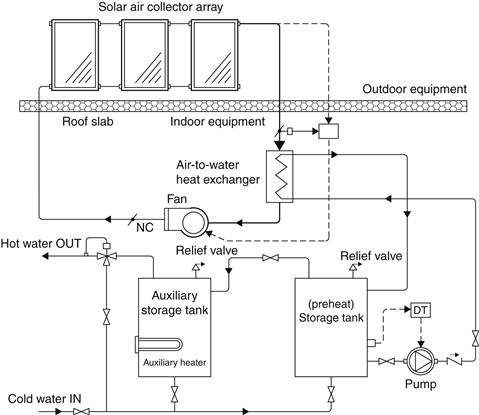
FIGURE 5.14 Air water-heating system.
The advantages of this system are that air does not need to be protected from freezing or boiling, is non-corrosive, does not suffer from heat transfer fluid degradation, and is free. Additionally, the system is more cost-effective because no safety values or expansion vessels are required. The disadvantages are that air-handling equipment (ducts and fans) needs more space than piping and pumps, air leaks are difficult to detect, and parasitic power consumption (electricity used to drive the fans) is generally higher than that of liquid systems.
5.2.4 Heat pump systems
Heat pumps use mechanical energy to transfer thermal energy from a source at a lower temperature to a sink at a higher temperature. The bigger advantage of electrically driven heat pump heating systems, compared to electric resistance heating or expensive fuels, is that the heat pump’s coefficient of performance (ratio of heating performance to electrical energy) is greater than unity for heating; so it yields 9–15 MJ of heat for each kilowatt hour of energy supplied to the compressor, which saves on purchase of energy.
The original system concept, proposed by Charters et al. (1980), was a system with direct evaporation of the working fluid of the heat pump in the solar collector. The condenser of the heat pump was actually a heat exchanger wrapped around the storage tank. In this way, the initial system cost and the parasitic energy requirements of the system are minimized. A possible disadvantage of this system is that the condenser heat transfer is limited by the free convection from the tank wall, which can be minimized by using a large heat transfer area in the tank. A more important disadvantage of this system is that the heat pump refrigeration circuit must be evacuated and charged on site, which requires special equipment and expertise.
This disadvantage is removed by using compact solar heat pump systems. These incorporate an evaporator mounted outside the water storage tank with natural convection air circulation. This system needs to be installed outdoors, and if installed adjacent to the ventilation duct outlet of a building, it can also work as a waste heat recovery unit. The advantages of this system are that it has no parasitic energy requirement and, because the system is packaged, all its components are assembled in the factory and thus the system is precharged. The installation of this system is as simple as a conventional electric water heater because the unit requires no high-power electrical connection (Morrison, 2001).
5.2.5 Pool heating systems
Solar pool-heating systems require no separate storage tank, because the pool itself serves as storage. In most cases, the pool’s filtration pump is used to circulate the water through solar panels or plastic pipes. For a daylong operation, no automatic controls are required, because the pool usually operates when the sun is shining. If such controls are employed, they are used to direct the flow of filtered water to the collectors only when solar heat is available. This can also be achieved by a simple manually operated valve. Normally, these kinds of solar systems are designed to drain down into the pool when the pump is switched off; thus the collectors are inherently freeze protected (ASHRAE, 2007).
The primary type of collector design used for heating swimming pools is the rigid black plastic panels made from polypropylene (see Chapter 3, Section 3.1.1). Additionally, plastic pipes or tube-on-sheet panels can be used. In all cases, however, a large area is required and the roof of a nearby building can be used for this purpose.
Recommendations for the design, installation, and commissioning of solar heating systems for swimming pools, using direct circulation of pool water to the solar collectors, are given in the technical report ISO/TR 12596:1995 (1995a). The report does not deal with the pool filtration system to which a solar heating system is often connected. The material presented in the report is applicable to all sizes of pools, both domestic and public, that are heated by solar energy, either alone or in conjunction with a conventional system. Additionally, the report includes details of the heating load calculations. The pool heating load is the total heat loss less any heat gains from incident radiation.
The total heat loss is the sum of losses due to evaporation, radiation, and convection. This calculation requires knowledge of the air temperature, wind speed, and relative humidity or partial vapor pressure. Other causes of heat losses, which have a much smaller effect, are turbulence caused by swimmers, conduction to the ground (usually neglected), and rainfall, which at substantial quantities can lower the pool temperature. The addition of make-up water should be considered if the temperature differs considerably from the pool operating temperature. Pools usually operate in a narrow temperature range of 24–32 °C. Since the pool has a large mass, its temperature does not change quickly.
The use of a pool cover reduces heat losses, particularly evaporative losses; however, when designing a solar pool-heating system, it is often not possible to know with certainty the times during which a cover will be in place. In addition, the cover may not have a perfect fit. Hence, a conservative approach should be taken when allowing for the effect of a cover (ISO/TR, 1995a).
Evaporation heat loss
The following analysis is for a still pool as per ISO/TR 12596:1995 (1995a). The evaporative heat loss from a still outdoor pool is a function of the wind speed and of the vapor pressure difference between the pool water and the atmosphere, given by:
![]() (5.18)
(5.18)
qe = heat loss by evaporation (MJ/m2 day);
Pw = saturation water vapor pressure at water temperature, tw (kPa);
Pa = partial water vapor pressure in the air (kPa); and
v0.3 = wind speed velocity at a height of 0.3 m above the pool (m/s).
If the wind velocity above the pool cannot be measured, it can be obtained from climatic data by the application of a reduction factor for the degree of wind shelter at the pool. Usually, the wind speed is measured at 10 m from the ground (v10); therefore,
For normal suburban sites, v = 0.30v10
For well-sheltered sites, v = 0.15v10
For indoor pools, the low air velocity results in a lower evaporation rate than usually occurs in outdoor pools, and the evaporative heat loss is given by:
![]() (5.19)
(5.19)
Penc = the partial water vapor pressure in the pool enclosure (kPa);
vs = air speed at the pool water surface, typically 0.02–0.05 (m/s).
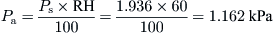
Partial water vapor pressure (Pa) can be calculated from the relative humidity,
![]() (5.20)
(5.20)
Ps = saturation water vapor pressure at air temperature, ta (kPa).
Saturation water vapor pressure can be obtained from:
![]() (5.21)
(5.21)
The presence of swimmers in a pool significantly increases the evaporation rate. With five swimmers per 100 m2, the evaporation rate has to increase by 25–50%. With 20–25 swimmers per 100 m2, the evaporation rate has to increase by 70–100% more than the value for a still pool.
Radiation heat loss
Radiation heat loss is given by:
![]() (5.22)
(5.22)
qr = radiation heat loss (MJ/m2 day);
εw = longwave emissivity of water = 0.95;
hr = radiation heat transfer coefficient (W/m2 K).
The radiation heat transfer coefficient is calculated from:
![]() (5.23)
(5.23)
For an indoor pool, Ts = Tenc, both in Kelvins, and Tenc is the temperature of the walls of the pool enclosure. For an outdoor pool,
![]() (5.24)
(5.24)
where sky emissivity, εs, is a function of dew point temperature, tdp, given by (ISO, 1995b):
![]() (5.25)
(5.25)
It should be noted that Ts might vary from Ts ≈ Ta for cloudy skies to Ts ≈ Ta − 20 for clear skies.
Convection heat loss
Heat loss due to convection to ambient air is given by:
![]() (5.26)
(5.26)
qc = convection heat loss to ambient air (MJ/m2 day);
v = wind velocity at 0.3 m above outdoor pools or over the pool surface for indoor pools (m/s);
tw = water temperature (°C); and
As can be seen from Eq. (5.26), the convective heat loss depends to a large extent on the wind velocity. During summer for outdoor pools, this may be negative, and in fact, the pool will gain heat by convection from the air.
Make-up water
If the make-up water temperature is different from the pool operating temperature, there will be a heat loss, given by:
![]() (5.27)
(5.27)
qmuw = make-up water heat loss (MJ/m2 day);
mevp = daily evaporation rate (kg/m2 day);
tmuw = temperature of make-up water (°C); and
cp = specific heat of water (J/kg °C).
The daily evaporation rate is given by:
![]() (5.28)
(5.28)
hfg = latent heat of vaporization of water (MJ/kg).
Solar radiation heat gain
Heat gain due to the absorption of solar radiation by the pool is given by:
![]() (5.29)
(5.29)
qs = rate of solar radiation absorption by the pool (MJ/m2 day);
α = solar absorptance (α = 0.85 for light-colored pools; α = 0.90 for dark-colored pools); and
Ht = solar irradiation on a horizontal surface (MJ/m2 day).
It should be noted that the solar absorptance, α, is dependent on the color, depth, and pool usage. For pools with continuous intensive use (public pools), an additional reduction of 0.05 should be made to the absorption factor (ISO/TR, 1995a).
EXAMPLE 5.1
A 500 m2 light-colored swimming pool is located in a normal suburban site, where the measured wind speed at 10 m height is 3 m/s. The water temperature is 25 °C, the ambient air temperature is 17 °C, and relative humidity is 60%. There are no swimmers in the pool, the temperature of the make-up water is 22 °C, and the solar irradiation on a horizontal surface for the day is 20.2 MJ/m2 day. How much energy must the solar system supply (Qss) to the pool to keep its temperature at 25 °C?
Solution
The energy balance of the pool is given by:

The velocity at 0.3 m above the pool surface is 0.3 × 3 = 0.9 m/s. The partial pressures for air and water are given by Eqs (5.20) and (5.21). The saturation water vapor pressure at air temperature, ta, is also given by Eq. (5.21); therefore,

From Eq. (5.20),
Saturation water vapor pressure can also be obtained from Eq. (5.21) by using tw instead of ta. Therefore,

From Eq. (5.18), evaporation heat losses are:

From Eq. (5.25),

From Eq. (5.24),

From Eq. (5.22), radiation heat losses are:

From Eq. (5.26), convection heat losses are:

From steam tables, hfg, the latent heat of vaporization of water at 25 °C is equal to 2441.8 kJ/kg. Therefore, the daily evaporation rate is given by Eq. (5.28):
From Eq. (5.27), the heat losses due to the make-up water are:

From Eq. (5.29), solar radiation heat gain is:

Therefore, the energy required by the solar system to keep the pool at 25 °C is:

Leave a Reply