One of the most important components of an active solar energy system is the temperature controller because a faulty control is usually the cause of poor system performance. In general, control systems should be as simple as possible and should use reliable controllers, which are available nowadays. One of the critical parameters that need to be decided by the designer of the solar system is where to locate the collector, storage, over-temperature, and freezing-temperature sensors. The use of reliable, good-quality devices is required for many years of trouble-free operation. As was seen in the previous sections of this chapter, the control system should be capable of handling all possible system operating modes, including heat collection, heat rejection, power failure, freeze protection, and auxiliary heating.
The basis of solar energy system control is the differential temperature controller (DTC), shown as just DT in diagrams presented earlier in this chapter. This is simply a fixed temperature difference (ΔT) thermostat with hysteresis. The differential temperature controller is a comparing controller with at least two temperature sensors that control one or more devices. Typically, one of the sensors is located at the top side of the solar collector array and the second at the storage tank (Figure 5.30). On unpressurized systems, other DTCs may control the extraction of heat from the storage tank. Most other controls used in solar energy systems are similar to those for building services systems.
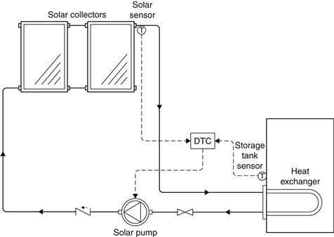
FIGURE 5.30 Basic collector control with a differential temperature controller.
The DTC monitors the temperature difference between the collectors and the storage tank. When the temperature of the solar collectors exceeds that of the tank by a predetermined amount (usually 4–11 °C), the DTC switches the circulating pump on. When the temperature of the solar collectors drops to 2–5 °C above the storage temperature, the DTC stops the pump. Instead of controlling the solar pump directly, the DTC can operate indirectly through a control relay to operate one or more pumps and possibly perform other control functions, such as the actuation of control valves.
The temperature differential set point of the differential temperature controller may be fixed or adjustable. If the controller set point is fixed, the controller selected should correspond to the requirements of the solar system. An adjustable differential set point makes the controller more flexible and allows it to be adjusted to the specific system or conditions of the solar system, i.e., different setting in summer and winter. The optimum differential on set point is difficult to calculate, because of the changing variables and conditions. Typically, the turn-on set point is 5–9 °C above the off set point. The optimum on set point is a balance between optimum energy collection and the avoidance of short starts and stops of the pump. The optimum turn-off temperature differential should be the minimum possible, which depends on whether there is a heat exchanger between the collectors and storage tank.
Frequent starts and stops of the pump, also called short cycling, must be minimized because they can lead to premature pump failure. Short cycling depends on how quickly and how often the solar collector sensor temperature exceeds the on set point and drops below the off set point. This is influenced by the insolation intensity, the pump flow rate, the solar collector thermal mass, the response of the sensor, and the temperature of the fluid entering the collector. What happens in practice is that the water in the collector starts warming up as soon as the off-condition is reached and the flow stops. As the water heats up, it eventually reaches the on set point, at which point the pump is switched on and fluid circulates through the collector. Therefore, the hot fluid in the collector is pushed into the return manifold and replaced by relatively cool water from the supply manifold, which is warmed as it moves through the collector. A short cycle of the pump may mean that the hot water will never reach the storage tank, especially if the return pipe is long. The most common method of avoiding short cycling is the use of wide temperature difference between the on- and off set points. This, however, leads to the requirement of a lot of insolation to switch the pump on, which loses energy in the collector and may never reach the on set point in periods of low insolation. Therefore, the guidelines given in this section must be followed for deciding the correct setting.
If the system does not have a heat exchanger, a range of 1–4 °C is acceptable for the off set point. If the system incorporates a heat exchanger, a higher differential temperature set point is used to have an effective heat transfer, i.e., a higher-energy transfer between the two fluids. The minimum, or off, temperature differential is the point at which the cost for pumping the energy is equal to the cost of the energy being pumped, in which case the heat lost in the piping should also be considered. For systems with heat exchangers, the off set point is generally between 3 and 6 °C.
In closed-loop systems, a second temperature sensor may be used in the tank above the heat exchanger to switch the pump between low and high speed and hence provide some control of the return temperature to the tank heat exchanger. Furbo and Shah (1997) evaluated the use of a pump with a controller that varies the flow proportionally to the working fluid temperature and found that its effect on system performance is minor.
In the following analysis, the collector sensor is considered to be placed on the collector absorber plate. Using the concept of absorbed radiation, when the collector pump is off, the useful output from the collector is 0 and the absorber plate is at an equilibrium temperature given by:
![]() (5.71)
(5.71)
Therefore, the value of S when the plate temperature, Tp, is equal to Ti + ΔTON is:
Using Eq. (3.60) with the absorbed solar radiation, when the pump is on, the useful gain from the collector is:
![]() (5.73)
(5.73)
If we substitute Eq. (5.72) into Eq. (5.73),
![]() (5.74)
(5.74)
However, the useful energy when the pump is on is also given by:
![]() (5.75)
(5.75)
In fact, the temperature difference (To − Ti), by ignoring heat losses from the pipes, is the difference seen by the DTC once the flow is turned on. Consequently, by combining Eqs (5.74) and (5.75), the off set point must satisfy the following inequality because otherwise the system will become unstable:
![]() (5.76a)
(5.76a)
If the system has a collector heat exchanger then Eq. (5.50) is used instead of Eq. (5.75) and the inequality becomes:
![]() (5.76b)
(5.76b)
5.5.1 Placement of sensors
Proper placement of the collector temperature sensor is important for a good system operation. The sensor must have a good thermal contact with the collector plate or piping. Collector sensors may be located on the collector plate, on a pipe near the collector, or in the collector outlet pipe. The best of all is on the collector plate, but this is not the easiest, because dismantling and modification on one collector of the array is required, which would need to be done on site. The easiest and perhaps the best point for the location of the sensor is on the pipe leaving the collector. Usually a T piece is used and the sensor is placed in a deep well with a few drops of oil, which ensures good contact, as shown in Figure 5.31(a), or on the side of the T piece, as shown in Figure 5.31(b).
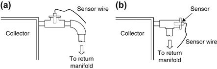
FIGURE 5.31 Placement of collector sensor. (a) Deep well. (b) Side of T piece.
The storage tank sensor should be located near the bottom of the storage tank, at about one third of its height. If the system uses an internal heat exchanger, the sensor is located above the heat exchanger. Ideally, this sensor should identify if there is still water in the tank, which can be heated by solar energy. Therefore, the location indicated is considered a good compromise because a lower location would give a false reading even with the slightest demand, which will be replaced by make-up (cold) water, whereas a higher location would leave a lot of water at a low temperature, even if solar energy is available.
A freeze protection sensor, if used, should be located in such a position so as to detect the coldest liquid temperature. Two suitable locations are the back of the absorber plate and the entry pipe to the collector from the supply manifold. For the reasons indicated previously, the latter is preferred. The over-temperature sensor can be located either at the top part of the storage tank or on the collector exit pipe. For the latter, the sensor is located in a similar location and manner as the collector temperature sensor.
Leave a Reply