Thermal storage is one of the main parts of a solar heating, cooling, and power generating system. Because for approximately half the year any location is in darkness, heat storage is necessary if the solar system must operate continuously. For some applications, such as swimming-pool heating, daytime-air heating, and irrigation pumping, intermittent operation is acceptable, but most other uses of solar energy require operating at night and when the sun is hidden behind clouds.
Usually the design and selection of the thermal storage equipment is one of the most neglected elements of solar energy systems. It should be realized, however, that the energy storage system has an enormous influence on an overall system cost, performance, and reliability. Furthermore, the design of the storage system affects the other basic elements, such as the collector loop and the thermal distribution system.
A storage tank in a solar system has several functions, the most important of which are:
• Improvement of the utilization of collected solar energy by providing thermal capacitance to alleviate the solar availability and load mismatch and improve the system response to sudden peak loads or loss of solar input.
• Improvement of system efficiency by preventing the array heat transfer fluid from quickly reaching high temperatures, which lower the collector efficiency.
Generally, solar energy can be stored in liquids, solids, or phase-change materials (PCM). Water is the most frequently used storage medium for liquid systems, even though the collector loop may use water, oils, water–glycol mixtures, or any other heat transfer medium as the collector fluid. This is because water is inexpensive and non-toxic and it has a high storage capacity, based on both weight and volume. Additionally, as a liquid, it is easy to transport using conventional pumps and plumbing. For service water-heating applications and most building space heating, water is normally contained in some type of tank, which is usually circular. Air systems typically store heat in rocks or pebbles, but sometimes the structural mass of the building is used.
An important consideration is that the temperature of the fluid delivered to the load should be appropriate for the intended application. The lower the temperature of the fluid supplied to the collectors, the higher is the efficiency of the collectors.
The location of the storage tank should also be given careful consideration. The best location is indoors, where thermal losses are minimal and weather deterioration will not be a factor. If the tank cannot be installed inside the building, then it should be located outside above the ground or on the roof. Such a storage tank should have a good insulation and good outside protection of the insulation. The storage tank should also be located as close as possible to the collector arrays to avoid long pipe runs.
5.3.1 Air system thermal storage
The most common storage media for air collectors are rocks. Other possible media include PCM, water, and the inherent building mass. Gravel is widely used as a storage medium because it is abundant and relatively inexpensive.
In cases where large interior temperature swings can be tolerated, the inherent structure of the building may be sufficient for a thermal storage. Loads requiring no storage are usually the most cost-effective applications of air collectors, and heated air from the collectors can be distributed directly to the space. Generally, storage may be eliminated in cases where the array output seldom exceeds the thermal demand (ASHRAE, 2004).
The main requirements for a gravel storage are good insulation, low air leakage, and low pressure drop. Many different designs can fulfill these requirements. The container is usually constructed from concrete, masonry, wood, or a combination of these materials. Airflow can be vertical or horizontal. A schematic diagram of a vertical flow bed is shown in Figure 5.15. In this arrangement, the solar-heated air enters at the top and exits from the bottom. This tank can work as effectively as a horizontal flow bed. In these systems, it is important to heat the bed with the hot airflow in one direction and to retrieve the heat with airflow in the opposite direction. In this way, pebble beds perform as effective counterflow heat exchangers.
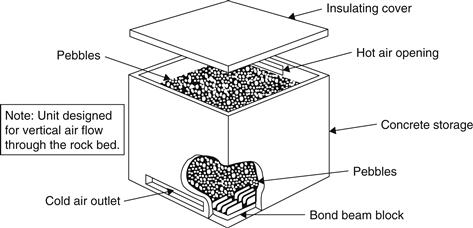
FIGURE 5.15 Vertical flow packed rock bed.
The size of the rocks for pebble beds range from 35 to 100 mm in diameter, depending on airflow, bed geometry, and desired pressure drop. The volume of the rocks needed depends on the fraction of collector output that must be stored. For residential systems, storage volume is typically in the range of 0.15–0.3 m3 per square meter of collector area. For large systems, pebble beds can be quite large and their large mass and volume may lead to location problems.
Other storage options for air systems include PCMs and water. PCMs are functionally attractive because of their high volumetric heat storage capabilities, since they require only about one tenth the volume of a pebble bed (ASHRAE, 2004).
Water can also be used as a storage medium for air collectors through the use of a conventional air-to-water heat exchanger to transfer heat from the air to the water in the storage tank. This option has two advantages:
1. Water storage is compatible with hydronic heating systems.
2. It is relatively compact; the required storage water volume is roughly one third the pebble bed’s volume.
5.3.2 Liquid system thermal storage
Two types of water storage for liquid systems are available: pressurized and unpressurized. Other differentiations include the use of an external or internal heat exchanger and single or multiple-tank configurations. Water may be stored in copper, galvanized metal, or concrete tanks. Whatever storage vessel is selected, however, this should be well insulated and large tanks should be provided with internal access for maintenance. Recommended U value is ≈0.16 W/m2 K.
Pressurized systems are open to city mains water supply. Pressurized storage is preferred for small service water-heating systems, although in cases like Cyprus, where the water supply is intermittent, it is not suitable. Typical storage size is about 40–80 l per square meter of collector area. With pressurized storage, the heat exchanger is always located on the collector side of the tank. Either internal or external heat exchanger configurations can be used. Two principal types of internal heat exchangers exist: an immersed coil and a tube bundle, as shown in Figure 5.16.
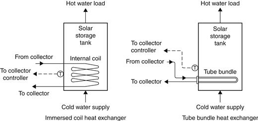
FIGURE 5.16 Pressurized storage with internal heat exchanger.
Sometimes, because of the required storage volume, more than one tank is used instead of one large one, if such a large-capacity tank is not available. Additional tanks offer, in addition to the extra storage volume, increased heat exchanger surface (when a heat exchanger is used in each tank) and reduced pressure drop in the collection loop. A multiple-tank configuration for pressurized storage is shown in Figure 5.17. It should be noted that the heat exchangers are connected in a reverse-return mode to improve flow balance.
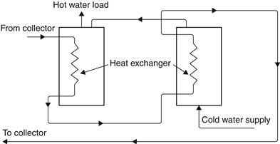
FIGURE 5.17 Multiple-tank storage arrangement with internal heat exchangers.
An external heat exchanger provides greater flexibility because the tank and the exchanger can be selected independently of other equipment (see Figure 5.18). The disadvantage of this system is the parasitic energy consumption, in the form of electrical energy, that occurs because of the additional pump.
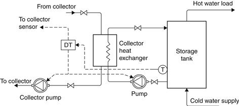
FIGURE 5.18 Pressurized storage system with external heat exchanger.
For small systems, an internal heat exchanger tank arrangement is usually used, which has the advantage of preventing the water side of the heat exchanger from freezing. However, the energy required to maintain the water above freezing is extracted from storage, and thus the overall system performance is decreased. With external heat exchanger, a bypass can be arranged to divert cold fluid around the heat exchanger until it has been heated to an acceptable level of about 25 °C (ASHRAE, 2004). When the heat transfer fluid is warmed to this level, it can enter the heat exchanger without causing freezing or extraction of heat from storage. If necessary, this arrangement can also be used with internal heat exchangers to improve performance.
For systems with sizes greater than about 30 m3, unpressurized storage is usually more cost-effective than pressurized. This system, however, can also be employed in small domestic flat-plate collector systems, and in this case, the make-up water is usually supplied from a cold water storage tank located on top of the hot water cylinder.
Unpressurized storage for water and space heating can be combined with the pressurized city water supply. This implies the use of a heat exchanger on the load side of the tank to isolate the high-pressure mains’ potable water loop from the low-pressure collector loop. An unpressurized storage system with an external heat exchanger is shown in Figure 5.19. In this configuration, heat is extracted from the top of the solar storage tank and the cooled water is returned to the bottom of the tank so as not to distract stratification. For the same reason, on the load side of the heat exchanger, the water to be heated flows from the bottom of the backup storage tank, where relatively cold water exists, and heated water returns to the top. Where a heat transfer fluid is circulated in the collector loop, the heat exchanger may have a double-wall construction to protect the potable water supply from contamination. A differential temperature controller (DTC) controls the two pumps on either side of the heat exchanger. When small pumps are used, both may be controlled by the same controller without overloading problems. The external heat exchanger shown in Figure 5.19 provides good system flexibility and freedom in component selection. In some cases, system cost and parasitic power consumption may be reduced by an internal heat exchanger.
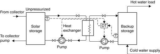
FIGURE 5.19 Unpressurized storage system with external heat exchanger.
Stratification is the collection of hot water to the top of the storage tank and cold water to the bottom. This improves the performance of the tank because hotter water is available for use and colder water is supplied to the collectors, which enables the collector to operate at higher efficiency.
Another category of hot water stores is the so-called solar combistores. These are used mainly in Europe for combined domestic hot water preparation and space heating. More details on these devices are included in Chapter 6, Section 6.3.1.
5.3.3 Thermal analysis of storage systems
Here the water and air systems are examined separately.
Water systems
For fully mixed or unstratified energy storage, the capacity (Qs) of a liquid storage unit at uniform temperature, operating over a finite temperature difference (ΔTs), is given by:
![]() (5.30)
(5.30)
M = mass of storage capacity (kg).
The temperature range over which such a unit operates is limited by the requirements of the process. The upper limit is also determined by the vapor pressure of the liquid.
An energy balance of the storage tank gives:
![]() (5.31)
(5.31)
Qu = rate of collected solar energy delivered to the storage tank (W);
Ql = rate of energy removed from storage tank to load (W); and
Qtl = rate of energy loss from storage tank (W).
The rate of storage tank energy loss is given by:
![]() (5.32)
(5.32)
(UA)s = storage tank loss coefficient and area product (W/°C);
Tenv = temperature of the environment where the storage tank is located (°C).
To determine the long-term performance of the storage tank, Eq. (5.31) may be rewritten in finite difference form as:
![]() (5.33)
(5.33)
or
![]() (5.34)
(5.34)
Ts−n = new storage tank temperature after time interval Δt (°C).
This equation assumes that the heat losses are constant in the period Δt. The most common time period for this estimation is an hour because the solar radiation data are also available on an hourly basis.
EXAMPLE 5.2
A fully mixed water storage tank contains 500 kg of water, has an UA product equal to 12 W/°C, and is located in a room that is at a constant temperature of 20 °C. The tank is examined in a 10 h period starting from 5 am where the Qu is equal to 0, 0, 0, 10, 21, 30, 40, 55, 65, 55 MJ. The load is constant and equal to 12 MJ in the first 3 h, 15 MJ in the next 3 h, and 25 MJ the rest of time. Find the final storage tank temperature if the initial temperature is 45 °C.
Solution
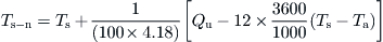
The estimation time interval is 1 h. Using Eq. (5.34) and inserting the appropriate constants, we get:

By inserting the initial storage tank temperature (45 °C), Qu, and Ql according to the problem, Table 5.3 can be obtained.So for the first hour at 5 am:

Table 5.3
Results for Example 5.2
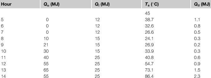
For the second hour at 6 am:

The rest of calculations are shown in Table 5.3.
Therefore, the final storage tank temperature is 86.4 °C. For these calculations, the use of a spreadsheet program is recommended.
The collector performance equations in Chapter 4 can also be used with the more detailed determination of inlet fluid temperature to estimate the daily energy output from the collector. This is illustrated by the following example.
EXAMPLE 5.3
Repeat Example 4.2 by considering the system to have a fully mixed storage tank of 100 l and no load. The initial storage tank temperature at the beginning of the day is 40 °C and the environmental temperature at the area where the storage tank is located is equal to the ambient air temperature. The tank UA value is 12 W/°C. Calculate the useful energy collected over the day.
Solution
By using Eq. (5.34), the new storage tank temperature can be considered as the collector inlet. This is correct for the present example but is not very correct in practice because some degree of stratification is unavoidable in the storage tank.
The results in this case are shown in Table 5.4. It should be noted that for the new storage tank temperature the useful energy collected and Ti from the previous time step is used. For example at 9 am:

where Qu = 719.6 kJ (estimated at 8 am using Kθ = 0.806 and It = 900 kJ/m2) and ΔT/Gt = (37.5 − 28)/(900/3.6) = 0.038.
Table 5.4
Example 5.3 Results
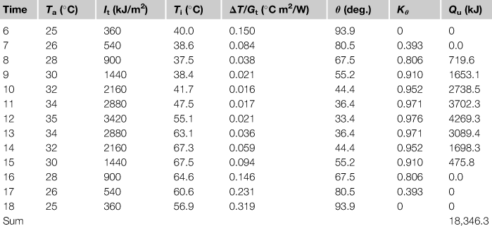
Therefore, the total energy collected over the day = 18,346.3 kJ.
As can be seen from the results of this example, the collector performance is somewhat lower than those of Example 4.2 because a higher collector inlet temperature leads to lower collector efficiency. In this example, too, the use of a spreadsheet program greatly facilitates estimations.
The density of water (and other fluids) drops as its temperature increases. When hot water enters from the collectors and leaves for the load from the top of the tank and cool water flows (cold water returns to the collector and make-up water supply) occur at the bottom, the storage tank will stratify because of the density difference. Additionally, with cool water at the tank bottom, the temperature of water fed to the collector inlet is low, and thus the collector performance is enhanced. Moreover, water from the top of the tank, which is at the highest temperature, may meet the heating demand more effectively. The degree of stratification is measured by the temperature difference between the top and bottom of the storage tank and is crucial for the effective operation of a solar system.
There are basically two types of models developed to simulate stratification: the multimode and the plug flow. In the former, the tank modeled is divided into N nodes (or sections) and energy balances are written for each node. This results in a set of N differential equations, which are solved for the temperatures of the N nodes as a function of time. In the latter, segments of liquid of various temperatures are assumed to move through the storage tank in plug-flow and the models keep track of the size, temperature, and position of the segments. Neither of these methods is suitable for hand calculations; however, more details of the plug flow model are given here.
The procedure is presented by Morrison and Braun (1985) and is used in conjunction with TRNSYS thermosiphon model presented in Section 5.1.1. This model produces the maximum degree of stratification possible. The storage tank is initially represented by three fluid segments. Initially, the change of tank segment temperatures, due to heat loss to the surroundings and conduction between segments, is estimated. The energy input from the collector is determined by considering a constant temperature plug of fluid of volume ![]() entering the tank during the time step
entering the tank during the time step ![]() t. The plug of fluid entering the tank is placed between existing segments chosen to avoid developing a temperature inversion.
t. The plug of fluid entering the tank is placed between existing segments chosen to avoid developing a temperature inversion.
The load flow is considered in terms of another segment of fluid of volume, ![]() , and temperature TL, added either to the bottom of the tank or at its appropriate temperature level. Fluid segments are moved up the tank as a result of the addition of the new load flow segment. The net shift of the profile in the tank above the collector return level is equal to the load volume, VL, and that below the collector return is equal to the difference between the collector and load volumes (Vh − VL). After adjusting for the load flow, the auxiliary input is considered, and if sufficient energy is available, segments above the auxiliary input level are heated to the set temperature. According to the situation, the segment containing the auxiliary element is split so that only segments of the tank above the element are heated.
, and temperature TL, added either to the bottom of the tank or at its appropriate temperature level. Fluid segments are moved up the tank as a result of the addition of the new load flow segment. The net shift of the profile in the tank above the collector return level is equal to the load volume, VL, and that below the collector return is equal to the difference between the collector and load volumes (Vh − VL). After adjusting for the load flow, the auxiliary input is considered, and if sufficient energy is available, segments above the auxiliary input level are heated to the set temperature. According to the situation, the segment containing the auxiliary element is split so that only segments of the tank above the element are heated.
Segments and fractions of segments in the new tank profile that are outside the bounds of the tank are returned to the collector and load. The average temperature of the fluid delivered to the load is given by:
![]() (5.35)
(5.35)
where j and a must satisfy:
![]() (5.36)
(5.36)
and 0 ≤ a < 1.
The average temperature of fluid returned to the collector is:
![]() (5.37)
(5.37)
where n and b must satisfy:
![]() (5.38)
(5.38)
The main advantage of this tank model is that small fluid segments are introduced when stratification is developing, while zones of uniform temperature, such as those above the auxiliary heater, are represented by large fluid segments. Additionally, the size of fluid segments used to represent the tank temperature stratification varies with collector flow rate. If the collector flow rate is high, there will be little stratification in the preheat portion of the tank and the algebraic model will produce only a few tank segments. If the collector flow rate is low and the tank is stratified, then small tank segments will be generated. Generally, the number of segments generated in this model is not fixed but depends on many factors, such as the simulation time step, the size of the collector, load flow rates, heat losses, and auxiliary input. To avoid generating an excessive number of segments, adjacent segments are merged if they have a temperature difference of less than 0.5 °C.
Air systems
As we have seen before, in air systems, pebble beds are usually employed for energy storage. When solar radiation is available, hot air from the collectors enters the top of the storage unit and heats the rocks. As the air flows downward, heat transfer between the air and the rocks results in a stratified distribution of the pebbles, having a high temperature at the top and a low one at the bottom. This is the charging mode of the storage unit. When there is a heating demand, hot air is drawn from the top of the unit and cooler air is returned to the bottom of the unit, causing the bed to release its stored energy. This is the discharge mode of the pebble-bed storage unit. From this description, it can be realized that the two modes cannot occur at the same time. Unlike water storage, the temperature stratification in pebble-bed storage units can be easily maintained.
In the analysis of rock bed storage, it should be taken into account that both the rocks and air change temperature in the direction of airflow and there are temperature differentials between the rocks and air. Therefore, separate energy balance equations are required for the rocks and air. In this analysis, the following assumptions can be made:
1. Forced airflow is one-dimensional.
2. System properties are constant.
3. Conduction heat transfer along the bed is negligible.
4. Heat loss to the environment does not occur.
Therefore, the thermal behavior of the rocks and air can be described by the following two-coupled partial differential equations (Hsieh, 1986):
![]() (5.39)
(5.39)
![]() (5.40)
(5.40)
A = cross-sectional area of storage tank (m2);
Tb = temperature of the bed material (°C);
Ta = temperature of the air (°C);
ρb = density of bed material (kg/m3);
cb = specific heat of bed material (J/kg K);
ca = specific heat of air (J/kg K);
x = position along the bed in the flow direction (m);
![]() = mass flow rate of air (kg/s);
= mass flow rate of air (kg/s);
ε = void fraction of packing = void volume/total volume of bed (dimensionless); and
hv = volumetric heat transfer coefficient (W/m3 K).
An empirical equation for the determination of the volumetric heat transfer coefficient (hv) is:
![]() (5.41)
(5.41)
G = air mass velocity per square meter of bed frontal area (kg/s m2).
If the energy storage capacity of the air within the bed is neglected, Eq. (5.40) is reduced to:
![]() (5.42)
(5.42)
Equations (5.39) and (5.42) can also be written in terms of the number of transfer units (NTU) as:
![]() (5.43)
(5.43)
![]() (5.44)
(5.44)
The dimensionless NTU is given by:
![]() (5.45)
(5.45)
The parameter θ, which is also dimensionless in Eq. (5.43), is equal to:
![]() (5.46)
(5.46)
For the long-term study of solar air-storage systems, the two-coupled partial differential equations, Eqs (5.43) and (5.44), can be solved by a finite difference approximation with the aid of a computer.
Leave a Reply