Passive solar heating systems require little, if any, non-renewable energy to function. Every building is passive in the sense that the sun tends to warm it during the day and it loses heat at night. Passive systems incorporate the solar energy collection, storage, and distribution into the architectural design of the building and make minimal or no use of mechanical equipment, such as fans, to deliver the collected energy. Passive solar heating, cooling, and lighting design must consider the building envelope and its orientation, the thermal storage mass, window configuration and design, the use of sun spaces, and natural ventilation.
As part of the design process, a preliminary analysis must be undertaken to investigate the possibilities for saving energy through solar energy and the selection of the appropriate passive technique. The first step to consider for each case investigated should include an analysis of the climatic data of the site and definition of the comfort requirements of the occupants and the way to meet them. The passive system can then be selected by examining both direct and indirect gains.
6.2.1 Building construction: thermal mass effects
Heat can be stored in the structural materials of the building to reduce the indoor temperature, reduce the cooling load peaks, and shift the time that maximum load occurs. The storage material is referred to as the thermal mass. In winter, during periods of high solar gain, energy is stored in the thermal mass, avoiding overheating. In the late afternoon and evening hours, when energy is needed, heat is released into the building, satisfying part of the heating load. In summer, the thermal mass acts in a similar way as in winter, reducing the cooling load peaks.
Heat gain in a solar house can be direct or indirect. Direct gain is the solar radiation passing through a window to heat the building interior, whereas an indirect gain is the heating of a building element by solar radiation and the use of this heat, which is transmitted inside the building, to reduce the heating load.
Indirect-gain solar houses use the south-facing wall surface of the structure to absorb solar radiation, which causes a rise in temperature that, in turn, conveys heat into the building in several ways. Glass has led to modern adaptations of the indirect-gain principle (Trombe et al., 1977).
By glazing a large south-facing, massive masonry wall, solar energy can be absorbed during the day and conduction of heat to the inner surface provides radiant heating at night. The mass of the wall and its relatively low thermal diffusivity delay the arrival of the heat at the indoor surface until it is needed. The glazing reduces the loss of heat from the wall back to the atmosphere and increases the collection efficiency of the system during the day.
Openings in the wall, near the floor, and near the ceiling allow convection to transfer heat to the room. The air in the space between the glass and the wall warms as soon as the sun heats the outer surface of the wall. The heated air rises and enters the building through the upper openings. Cool air flows through the lower openings, and convective heat gain can be established as long as the sun is shining (see Figure 6.4, later in the chapter). This design is often called the Trombe wall, from the name of the engineer Felix Trombe, who applied the idea in France.
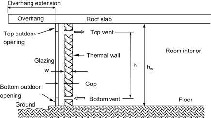
FIGURE 6.4 Schematic of the thermal storage wall.
In most passive systems, control is accomplished by moving a shading device that regulates the amount of solar radiation admitted into the structure. Manually operated window shades or Venetian blinds are the most widely used because of their simple control.
The thermal storage capabilities inherent in building mass can have a significant effect on the temperature within the space as well as on the performance and operation of heating, ventilating, and air-conditioning (HVAC) systems.
Effective use of structural mass for thermal storage has been shown to reduce the building energy consumption, reduce and delay peak heating and cooling loads (Braun, 1990), and in some cases, improve comfort (Simmonds, 1991). Perhaps the best-known use of thermal mass to reduce energy consumption is in buildings that include passive solar techniques (Balcomb, 1983).
The effective use of thermal mass can be considered incidental and allowed for in the heating or cooling design, or it may be considered intentional and form an integral part of the system design.
Incidental thermal mass effects
The principal thermal mass effect on heating and cooling systems serving spaces in heavyweight buildings is that a greater amount of thermal energy must be removed or added to bring the room to a suitable condition than for a similar lightweight building. Therefore, the system must either start conditioning the spaces earlier or operate at a greater output. During the occupied period, a heavyweight building requires a lower output because a higher proportion of heat gains or losses are absorbed by the thermal mass.
Advantage can be taken of these effects if low-cost electrical energy is available during the night so as to operate the air-conditioning system during this period to pre-cool the building. This can reduce both the peak and total energy required during the following day but might not always be energy efficient.
Intentional thermal mass effects
To make the best use of a thermal mass, the building should be designed with this objective in mind. Intentional use of the thermal mass can be either passive or active. Passive solar heating is a common application that utilizes the thermal mass of the building to provide warmth when no solar energy is available. Passive cooling applies the same principles to limit the temperature rise during the day. The spaces can be naturally ventilated overnight to absorb surplus heat from the building mass. This technique works well in moderate climates with a wide diurnal temperature swing and low relative humidity, but it is limited by the lack of control over the cooling rate.
The effective use of building structural mass for thermal energy storage depends on (ASHRAE, 2007):
1. The physical characteristics of the structure.
2. The dynamic nature of the building loads.
3. The coupling between the mass and zone air.
4. The strategies for charging and discharging the stored thermal energy.
Some buildings, such as frame buildings with no interior mass, are inappropriate for thermal storage. Many other physical characteristics of a building or an individual zone, such as carpeting, ceiling plenums, interior partitions, and furnishings, affect thermal storage and the coupling of the building with zone air (Kalogirou et al., 2002).
The term thermal mass is commonly used to signify the ability of materials to store significant amounts of thermal energy and delay heat transfer through a building component. This delay leads to three important results:
• The slower response time tends to moderate indoor temperature fluctuations under outdoor temperature swings (Brandemuehl et al., 1990).
• In hot or cold climates, it reduces energy consumption in comparison to that for a similar low-mass building (Wilcox et al., 1985).
• It moves building energy demand to off-peak periods because energy storage is controlled through correct sizing of the mass and interaction with the HVAC system.
Thermal mass causes a time delay in the heat flow, which depends on the thermo-physical properties of the materials used. To store heat effectively, structural materials must have high density (ρ), thermal capacity (C), and conductivity (k), so that heat may penetrate through all the material during the specific time of heat charging and discharging. A low value of the ρCk product indicates a low heat-storage capacity, even though the material can be quite thick.
Thermal mass can be characterized by the thermal diffusivity (a) of the building material, which is defined as:
![]() (6.38)
(6.38)
where cp is the specific heat of the material (J/kg °C).
Heat transfer through a material with high thermal diffusivity is fast, the amount of heat stored in it is relatively small, and the material responds quickly to changes in temperature. The effect of thermal mass on building behavior varies primarily with the climate at the building site and the position of the wall insulation relative to the building mass.
Thermal diffussivity is the controlling transport property for a transient heat transfer. The time lag for some common building materials of 300 mm thickness is 10 h for common brick, 6 h for face brick, 8 h for heavyweight concrete, and 20 h for wood because of its moisture content (Lechner, 1991). Thermal storage materials can be used to store direct energy by solar radiation in the building envelope or in places where incident radiation enters through openings in the building envelope. Also, these materials can be used inside the building to store indirect radiation, i.e., infrared radiation and energy from a room air convection.
The ideal climate for taking advantage of thermal mass is one that has large daily temperature fluctuations. The mass can be cooled by natural ventilation at night and be allowed to “float” during the warmer day. When outdoor temperatures are at their peak, the inside of the building remains cool because the heat has not yet penetrated the mass. Often, the benefits are greater during spring and fall, when some climates closely approximate this ideal case. In climates where heating is used extensively, thermal mass can be used effectively to collect and store solar gains or to store heat provided by the mechanical system, allowing the heating system to operate during off-peak hours (Florides et al., 2002b).
The distribution of thermal mass depends on the orientation of the given surface. According to Lechner (1991), a surface with a north orientation has little need for time lag, since it exhibits only small heat gains. East orientation surfaces need either a very long time lag, greater than 14 h, so that heat transfer is delayed until the late evening hours or a very short one, which is preferable because of the lower cost. South orientations can operate with an 8 h time lag, delaying the heat from midday until the evening hours. For west orientations, an 8 h time lag is again sufficient since they receive radiation for only a few hours before sunset. Finally, the roof requires a very long time lag since it is exposed to solar radiation during most hours of the day. However, because it is very expensive to construct heavy roofs, the use of additional insulation is usually recommended instead.
The effectiveness of thermal mass also increases by increasing the allowable temperature swing in the conditioned space (without the intervention of HVAC systems), so the mass has the opportunity to charge during warm hours and discharge during cooler periods.
The performance of thermal mass is influenced by the use of insulation. Where heating of the building is the major concern, insulation is the predominant effective envelope factor. In climates where cooling is of primary importance, thermal mass can reduce energy consumption, provided the building is unused in the evening hours and the stored heat can be dissipated during the night. In this case, either natural or mechanical ventilation can be used during the night, to introduce cool outdoor air into the space and remove heat from the massive walls and roof.
To model the complex interactions of all envelope components, computer simulations are necessary. These programs account for material properties of the components, building geometry, orientation, solar gains, internal gains, and HVAC control strategy. The calculations are usually performed on an hourly basis, using a full year of weather data.
Numerous models have been devised in the past to simulate the effect of thermal walls (Duffin and Knowles, 1985; Nayak, 1987; Zrikem and Bilgen, 1987). Also, a number of modeling techniques have been used to estimate the heat flow through a thermal wall. A simple analytical model was suggested by Duffin and Knowles (1985), in which all parameters affecting the wall performance can be analyzed. Smolec and Thomas (1993) used a two-dimensional model to compute the heat transfer, whereas Jubran et al. (1993) based their model on the finite difference method to predict the transient response, temperature distribution, and velocity profile of a thermal wall. The transient response of the Trombe wall was also investigated by Hsieh and Tsai (1988).
Characteristics of a thermal storage wall
A thermal storage wall is essentially a high-capacitance solar collector directly coupled to the room. Absorbed solar radiation reaches the room either by conduction through the wall to the inside wall surface from which it is convected and radiated into the room or by the hot air flowing though the air gap. The wall loses energy to the environment by conduction, convection, and radiation through the glazing covers.
A thermal storage wall is shown diagrammatically in Figure 6.4. Depending on the control strategy used, air in the gap can be exchanged with either the room air or the environment, or the flow through the gap can be stopped. The flow of air can be driven by a fan or be thermosiphonic, i.e., driven by higher air temperatures in the gap than in the room. Analytical studies of the thermosiphonic effect of air are confined to the case of laminar flow and neglect pressure losses in the inlet and outlet vents. Trombe et al. (1977) reported measurements of thermosiphon mass flow rates, which indicate that most of the pressure losses are due to expansion, contraction, and change of direction of flow, all associated with the inlet and outlet vents. For hot summer climates, a vent is provided at the upper part of the glazing (top-outdoor opening) to release the hot air produced in the gap between the glass and the thermal wall by drawing air from the inside of the room and by closing the top vent to the room. Alternatively the room can be completely isolated and use the bottom and top outdoor openings to cool the thermal wall without drawing air from the room.
In the Trombe wall model used in TRNSYS (see Chapter 11, Section 11.5.1), the thermosiphon air flow rate is determined by applying Bernoulli’s equation to the entire air flow system. For simplicity, it is assumed that the density and temperature of the air in the gap vary linearly with height. Solution of Bernoulli’s equation for the mean air velocity in the gap yields (Klein et al., 2005):
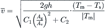 (6.39)
Ag = total gap cross-sectional area (m2);
C1 = vent pressure loss coefficient;
C2 = gap pressure loss coefficient;
g = acceleration due to gravity (m/s2); and
Tm = mean air temperature in the gap (K).
The term Ts is either Ta or TR, depending on whether air is exchanged with the environment (Ta) or the room (TR). The term C1(Ag/Av)2 + C2 represents the pressure losses of the system. The ratio (Ag/Av)2 accounts for the difference between the air velocity in the vents and the air velocity in the gap.
The thermal resistance (R) to energy flow between the gap and the room when mass flow rate ![]() is finite is given by:
is finite is given by:
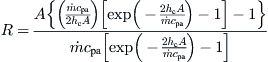 (6.40)
cpa = specific heat of air (J/kg °C); and
hc = gap air heat transfer coefficient (W/m2 K).
The value of hc, the heat transfer coefficient between the gap air and the wall and glazing, depends on whether air flows through the gap (Klein et al., 2005). For a no-flow rate (Randal et al., 1979),
![]() (6.41)
(6.41)
ka = air thermal conductivity (W/m °C);.
For a flow condition and Reynolds number, Re > 2000 (Kays, 1966),
![]() (6.42)
(6.42)
For a flow condition and Re ≤ 2000 (Mercer et al., 1967),
![]() (6.43a)
(6.43a)
where
![]() (6.43b)
(6.43b)
According to Figure 6.4, h is the distance between lower and upper openings (m) and w is the wall width (m).
Performance of thermal storage walls
A building with a thermal storage wall is shown in Figure 6.5(a), where Lm is the monthly energy loss from the building, Qaux is the auxiliary energy required to cover the load, QD is the excess absorbed energy above what is required to cover the load that cannot be stored and must be dumped, and ![]() is the mean room temperature, which is also equal to the low set point temperature setting of the room thermostat. The analysis of thermal storage walls is presented by Monsen et al. (1982) as part of the unutilizability method developed to design this type of systems, presented in Chapter 11, Section 11.4.2.
is the mean room temperature, which is also equal to the low set point temperature setting of the room thermostat. The analysis of thermal storage walls is presented by Monsen et al. (1982) as part of the unutilizability method developed to design this type of systems, presented in Chapter 11, Section 11.4.2.
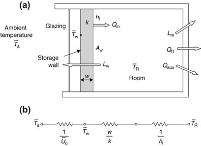
FIGURE 6.5 (a) Schematic of a thermal storage wall. (b) Equivalent electric circuit for the heat flow through the wall.
The monthly energy loss from the building, Lm, is defined as:
![]() (6.44)
(6.44)
(UA) = product of overall heat transfer coefficient and area of the building structure (W/°C);
![]() = rate of internal heat generation (W);
= rate of internal heat generation (W);
![]() = mean outdoor ambient temperature (°C); and
= mean outdoor ambient temperature (°C); and
![]() = mean indoor balance temperature (°C),
= mean indoor balance temperature (°C), ![]() .
.
The variable of integration in Eq. (6.44) is time t, and the plus sign indicates that only positive values are considered. If (UA) and ![]() are constant, Lm can be found from:
are constant, Lm can be found from:
![]() (6.45)
(6.45)
(DD)b = monthly degree-days evaluated at ![]() .
.
The monthly energy loss from the building through the thermal storage wall, Lw, assuming that the glazing has zero transmissivity for solar radiation, can be found from:
![]() (6.46)
(6.46)
Aw = thermal storage wall area (m2);
Uw = overall heat transfer coefficient of the thermal storage wall, including glazing (W/m2 °C); and
(DD)R = monthly degree-days evaluated at ![]() .
.
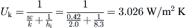
From Figure 6.5(b), the overall heat transfer coefficient of the thermal storage wall, including glazing, is given from:
![]() (6.47)
(6.47)
k = thermal conductivity of thermal storage wall (W/m °C);
hi = inside wall surface film coefficient, = 8.33 W/m2 °C [=1/0.12], from Table A5.5, Appendix 5; and
![]() = average overall heat transfer coefficient from the outer wall surface through the glazing to the ambient (W/m2 °C).
= average overall heat transfer coefficient from the outer wall surface through the glazing to the ambient (W/m2 °C).
Usually, night insulation is used to reduce the night heat losses. In this case, the average overall heat transfer coefficient ![]() is estimated as the time average of the daytime and nighttime values from:
is estimated as the time average of the daytime and nighttime values from:
![]() (6.48)
(6.48)
Uo = overall coefficient with no night insulation (W/m2 °C);
Rins = thermal resistance of insulation (m2 °C/W); and
F = fraction of time in which the night insulation is used.
A typical value of Uo for single glazing is 3.7 W/m2 °C and for double glazing is 2.5 W/m2 °C.
The monthly energy balance of the thermal storage wall gives:
![]() (6.49)
(6.49)
![]() = monthly average daily radiation per unit area incident on the wall (J/m2);
= monthly average daily radiation per unit area incident on the wall (J/m2);
![]() = monthly average transmittance of glazing and absorptance of wall product;
= monthly average transmittance of glazing and absorptance of wall product;
![]() = monthly average outer wall surface temperature; see Figure 6.5(a) (°C);
= monthly average outer wall surface temperature; see Figure 6.5(a) (°C);
![]() = monthly average room temperature (°C);
= monthly average room temperature (°C);
![]() = monthly average ambient temperature (°C);
= monthly average ambient temperature (°C);
Δt = number of seconds in a day; and
Uk = overall heat transfer coefficient from outer wall surface to indoor space (W/m2 °C).
The overall heat transfer coefficient from the outer wall surface to the indoor space can be obtained from:
![]() (6.50)
(6.50)
Equation (6.49) can be solved for monthly average outer wall surface temperature:
![]() (6.51)
(6.51)
Finally, the net monthly heat gain from the thermal storage wall to the building is obtained from:
![]() (6.52)
(6.52)
N = number of days in a month.
Methods for calculating the dump energy, QD, and auxiliary energy, Qaux, are presented in Chapter 11, Section 11.4.2.
EXAMPLE 6.3
A building has a south-facing thermal storage wall with night insulation Rins equal to 1.52 m2 K/W, applied for 8 h. Estimate the monthly heat transfer through the wall into the indoor space with and without night insulation for the month of December. The following data are given:
Solution
From Eq. (6.50), coefficient Uk can be calculated:
The two cases are now examined separately.
Without Night Insulation
From Eq. (6.51), we estimate the outer wall surface temperature ![]() :
:

From Eq. (6.52),

With night insulation
From Eq. (6.48) and by considering F = 8/24 = 0.333,

From Eq. (6.51), we estimate the outer wall surface temperature:

From Eq. (6.52).

So, by using night insulation, a considerable amount of loss is avoided and therefore more energy is transferred into the indoor space.
Use of phase change materials
Energy storage is enhanced with the use of phase change materials (PCMs), which change the phase of a material (usually from solid to liquid) and energy is stored in the form of latent heat, which is usually much larger than the sensible heat. Additionally, the change in phase is done at constant temperature according to the chemical composition of the material. These materials are usually microencapsulated into various building materials, like concrete, gypsum floor tiles and wallboard to increase thermal mass. Microencapsulation involves very small particles of PCM dispersed in the matrix of a building material. The usual material used for this purpose is paraffin wax, which contains n-octadecane with a melting point of 23 °C and heat of fusion of 184 kJ/kg, in gypsum.
The thermal improvements in a building due to the inclusion of PCMs depend on the climate, design and orientation of the construction, but also on the amount and type of PCM. Therefore, buildings employing PCM require a complete simulation of the thermal behavior of the designed space in the conditions of use carried out a priori.
Generally, PCM in buildings can be used for passive thermal energy storage in building envelopes and construction materials, for free-cooling and free-heating and for storing heat in solar air-heating systems.
Free-cooling is understood as a means to store ambient air coolness during the night, by solidifying the PCM, to supply cooling during the next day in summer. In fact the inside air of a building can be cooled down by exchanging heat with PCM. On the contrary, free-heating is understood as a means to store the solar radiation during daytime, by melting the PCM, to supply indoor heating during the night in winter. In principle, free-cooling or free-heating can keep the indoor air temperature in the comfortable region throughout the year if the thermo-physical properties of building envelope material are in the desired range. It has been found that with the help of PCM the indoor temperature fluctuations can be reduced significantly whilst maintaining desirable thermal comfort and decreasing the energy consumption.
In recent years the use of thermal energy storage in buildings with PCMs has become a topic with a lot of interest from the engineering community. Cabeza et al. (2011) presented a review of applications of PCMs in buildings. They also reviewed the requirements of the use of this technology, classification of materials, the phase change materials available and problems and possible solutions associated with the application of such materials in buildings.
Another important review is presented by Zhou et al. (2012), which covers investigations on thermal energy storage with PCMs in building applications, impregnation methods of PCM into construction materials, building applications and their thermal performance analyses, as well as numerical simulation of buildings with PCMs.
6.2.2 Building shape and orientation
The exposed surface area of a building is related to the rate at which the building gains or loses heat, while the volume is related to the ability of the building to store heat. Therefore, the ratio of volume to exposed surface area is widely used as an indicator of the rate at which the building heats up during the day and cools down at night. A high volume-to-surface ratio is preferable for a building that is desired to heat up slowly because it offers limited exposed surface for the control of both heat losses and gains (Dimoudi, 1997).
Building shape and orientation must be chosen in such a way so as to provide both heating and cooling. For heating, the designer must be careful to allow a solar access, i.e., allow the sun to reach the appropriate surfaces for the maximum possible hours, especially during the period from 9 am to 3 pm, which is the most useful energy period. For cooling, breeze and shading must be taken into consideration. The theoretical solar radiation impact for the various building surfaces can be obtained from appropriate tables, according to the time of the year and the surface orientation. From this analysis, the designer can select which surfaces should be exposed to or protected from the sun. Generally, south walls are the best solar collectors during wintertime but, together with the roof, they are the most problematic in summertime. With respect to shape, the best is the rectangular one with its long axis running in the east–west direction, because the south area receives three times more energy than the east or west. A square shape should be avoided, as well as the rectangular shape with its long axis running in the north–south direction.
One way to control the solar radiation reaching the building is to use trees that drop their leaves during winter in the sunlit area, such as south of the building. In this way, the sun reaches the surface in question during winter but the surface is in shade during summer.
6.2.3 Insulation
Insulation is a very important parameter to consider. In fact, before one considers any passive or active technique, the building must be well insulated to reduce thermal loads. The most important element of the building to insulate is the roof. This is very important for horizontal concrete roofs, which, during summertime, when the sun is higher in the sky, receive a considerable amount of radiation, which can increase the roof temperature considerably (Florides et al., 2000).
A good thermal insulation should ensure:
1. Healthy, comfortable and pleasant living without upsetting the thermal balance of the human body, which will satisfy the sense of comfort;
2. Economy in the consumption of energy by reducing the thermal losses from the building envelope;
3. Minimization of the initial cost for the installation of heating and cooling equipment;
4. Protection from noise as most thermal insulating materials are also sound insulators; and
5. Improved protection of the environment as a consequence of the reduced energy consumption of the building leading to lower GHG emissions.
The criteria that should be considered in the selection of the appropriate insulating material are:
b. Dependence of thermal conductivity on temperature
c. Dependence of thermal conductivity on humidity (the value of k increases substantially with moisture condensed in the mass of the thermal insulation)
e. Thermal expansion coefficient
a. Prefabricated materials or construction in situ
b. Protective measures required (protection from mechanical damages or environmental consequences)
a. Compression and bending stress
a. Resistance in corrosion, micro-organisms, and insects
b. Behavior in humidity (change of dimensions, permeance and moisture absorption)
c. Fire resistance and maximum operating temperature
d. Sensitivity to UV radiation exposure, various gases, seawater, etc.
a. Supply and installation cost
c. Percentage of added value for the whole construction
A question often raised when thermal insulation is to be applied is whether the insulation should be installed on the inside, outside of a building element (wall or roof) or in the middle of a wall. There are certain advantages and certain disadvantages in each case. Generally, internal insulation is used in cases where the heating or cooling system is required to achieve the required indoor condition very quickly and we are not interested in the performance of the space when the heating or cooling system is switched off. Examples include schools, offices operating during daytime and holiday houses.
The advantages of internal insulation include:
1. Simple and fast construction;
2. Lower cost compared to external insulation;
3. Immediate response of the heating and cooling system; and
4. Insulating materials do not need protection from the external conditions (wind, humidity, solar radiation, etc.).
1. Problem of indequate insulation and the creation of thermal bridges (items of the construction with inferior insulation allowing the passage of heat);
2. Quick loss of the indoor comfort conditions soon after an interruption of the heating or cooling system;
3. Possibility of surface condensation if vapor barrier is not installed;
4. Difficulty in hanging paintings, shelves, etc. on the walls;
5. Reduction of the useful internal building area; and
6. If applied on existing buildings, there is a disruption of the smooth operation of the building during installation.
External insulation is used in cases which do not require the immediate response of the building after switching on the heating or cooling system, but which demand good indoor comfort conditions long after the conditioning equipment has been switched off.
The advantages of external insulation include:
1. Conservation of good indoor conditions long after the heating or cooling equipment has been switched off due to the heat capacity of the building elements;
2. Bigger saving in energy due to the lowering of the operation time of the mechanical equipment;
3. Protection of the external surfaces from expansion and contraction because of the change in outdoor thermal conditions;
4. Minimization or non-existence of thermal bridges;
5. In case of an installation on the existing buildings, there is no interaction with the building operation.
1. Increased construction cost;
2. Care in construction is required (selection of proper materials and correct installation); and
3. Can be difficult to apply in buildings with many morphological features.
For the case of walls perhaps the more suitable installation for new buildings is to mount the insulation in between two layers of bricks either with or without an air gap. This solves most of the disadvantages of internal or external installation and combines the features of both constructions with respect to response time of the building to the mechanical heating and cooling, except the problem of thermal bridges. To avoid moisture migration in this construction an air gap is used between the external brick wall and the thermal insulation, which resists also the migration of moisture in the thermal insulation itself.
Another important measure often taken to increase the thermal insulation of buildings is to use a thermal barrier in double-glazed window aluminum frames. This is especially important in extreme environments and in cases where wide aluminum frames are used.
More details on this subject can be obtained from dedicated publications, such as the ASHRAE handbook series.
The way to account for insulation is by using Eq. (6.34), presented in Section 6.1.5, by incorporating the appropriate thickness and k value for the insulation used in a structure.
EXAMPLE 6.4
Consider the wall construction of Example 6.2 with the addition of 2.5 cm expanded polystyrene insulation. Estimate the new U value of the insulated wall construction.
Solution
The resistance value of the wall without insulation is 1.18 m2 °C/W (from Example 6.2). From Table A5.4 in Appendix 5, the thermal conductivity of expanded polystyrene is 0.041 W/m °C. Therefore, its resistance is 0.025/0.041 = 0.610 m2 °C/W. Therefore, the total resistance of the insulated wall construction is 1.18 + 0.610 = 1.79 m2 °C/W. Finally, the U value = 1/1.79 = 0.559 W/m2 °C.
6.2.4 Windows: sunspaces
The direct gain system is the simplest way of achieving passive heating. In this system, sunlight enters through windows or skylights and is absorbed by the inside surfaces of the building. In a direct gain system, thermal collection, dissipation, storage, and transfer of energy take place within the habitable space. This is the most effective of all passive concepts from the point of view of energy collection and simplicity. Additionally, this system allows the use of sun for lighting (daylight). Control of the system is very simple with the use of curtains and venetian blinds. The most serious drawback of the system is the possible deterioration of certain materials from sunlight.
Generally, daylighting is the illumination of the building interiors with sunlight and sky light and is known to affect visual performance, lighting quality, health, human performance, and energy efficiency. In terms of energy efficiency, daylighting can provide substantial energy reductions, particularly in non-residential applications through the use of electric lighting controls. Daylight can displace the need for electric light at the perimeter zone with vertical windows and at the core zone with skylights (Kalogirou, 2007).
A modern way of controlling daylight entering the building is with electrochromic windows. These have the ability to change their transmittance according to an input voltage, so the system can easily be automated. Another way is by using thermochromic windows, in which the reflectance and transmittance properties change at a specific critical temperature. At this temperature, the material undergoes a semiconductor-to-metal transition. At low temperature, the window allows all the sun’s energy to enter the room; above the critical temperature, it reflects the infrared portion of the sun’s energy. Hence, thermochromic windows could be used to significantly reduce the thermal load of buildings.
The use of windows for space heating can be done with the normal building windows or with sunspaces. Sunspaces are usually special rooms made from glass attached to a normal building room, located in the south direction. The sunspace carries out the functions of thermal collection, storage, and transfer into the normal building spaces. There are three types of sunspaces, as shown in Figure 6.6. The first uses just the south side of the building, the second uses the south side and part of the roof of the building, whereas the third is a semi-detached heating system for the main building and, in many cases, can be used as a greenhouse for growing plants. In the last type, because the sunspace is partially isolated from the main building, larger temperature swings can be accommodated in the sunspace than in a normal living room. The amount of energy received by the window surface is presented in the next section.
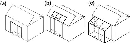
FIGURE 6.6 Various sunspace configurations.
When designing a sunspace, the objective is to maximize the winter solar radiation received and minimize the summer one. When the sunspace is integrated into the house, good night insulation has to be installed to protect the building spaces from excessive heating losses through the glass. If this is not possible, then double glazing should be used. The optimum orientation of a sunspace is due south, with variation of up to ±15° east or west being acceptable. Vertical glazing is preferred over sloped glazing, because it can be sealed more easily against leakages and reduces the tendency of sunspaces to overheat during summer. The performance of the vertical glazing, however, is about 15% lower than that of the optimally tilted glazing of equal area. A good compromise between vertical and sloped glazing is to use vertical glazing with some sloped portion (part of the roof), as shown in Figure 6.6(b).
In hot climates, where ventilation is a must, this can be done from the upper part of the sunspace. Therefore, the sunspace must be designed in such a way as to allow easy opening of some upper glass frames for ventilation.
6.2.5 Overhangs
Overhangs are devices that block direct solar radiation from entering a window during certain times of the day or the year. These are desirable for reducing the cooling loads and avoiding uncomfortable lighting in perimeter rooms due to excessive contrast. It would generally be advantageous to use long overhang projections in summer that could be retracted in winter, but in “real” buildings, the strategy is based not only on economic but also on aesthetic grounds.
To estimate the effect of the overhang length, the amount of shading needs to be calculated. For this purpose, the methodology presented in Chapter 2, Section 2.2.3, for the estimation of the profile angle, can be applied. By considering an overhang that extends far beyond the sides of the window, so as to be able to neglect the side effects, it is easier to estimate the fraction F (0 ≤ F ≤ 1) of the window that will be shaded by the overhang. By considering an overhang with a perpendicular projection, P, and gap, G, above a window of height H, as shown in Figure 6.7, the following relation developed by Sharp (1982) can be used:
![]() (6.53)
(6.53)
αc = solar altitude angle relative to the window aperture (°);
θc = incidence angle relative to the window aperture (°).
The fraction of the window that is sunlit can be obtained from:
![]() (6.54)
(6.54)
The solar altitude and incidence angles relative to the window aperture are given by:
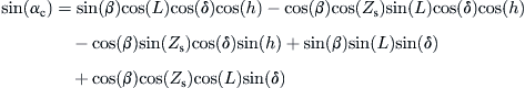 (6.55)
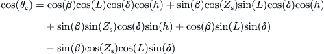 (6.56)
Zs = surface azimuth angle (°).
For the case of a vertical window shown in Figure 6.7(a), where the surface tilt angle is 90°, the angle αc is equal to the solar altitude angle α; therefore, Eqs (6.55) and (6.56) become the same as Eqs (2.12) and (2.19), respectively.
EXAMPLE 6.5
Estimate the shading fraction of a south-facing window 2 m in height, located in 40° latitude at 10 am and 3 pm solar times on June 16. The overhang is wide enough to neglect the side effects and its length is 1 m, located 0.5 m above the top surface of the window. The window is tilted 15° from vertical and faces due south.
Solution
From Example 2.6, on June 16, δ = 23.35°. The hour angle at 10 am is −30° and at 3 pm is 45°. From the problem data, we have P = 1 m, G = 0.5 m, H = 2 m, β = 75°, and Zs = 0°. Therefore, from Eqs (6.55) and (6.56) we have the following:
At 10 am:
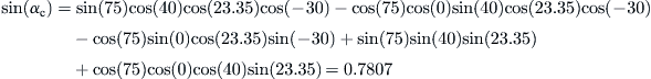
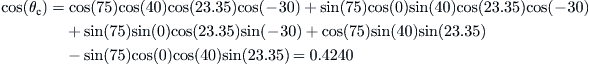
Therefore, from Eq. (6.53),

At 3 pm:
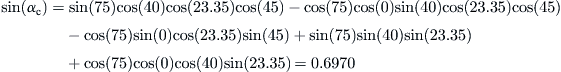
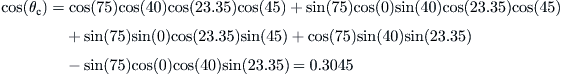
Therefore, from Eq. (6.53),

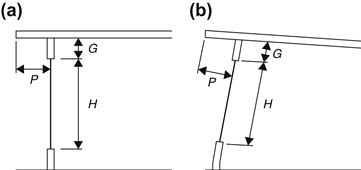
FIGURE 6.7 Window with overhang: (a) vertical window, (b) general case of tilted window.
The equation giving the area-average radiation received by the partially shaded window, by assuming that the diffuse and ground-reflected radiation is isotropic, is similar to Eq. (2.97):
![]() (6.57)
(6.57)
where the three terms represent the beam, diffuse, and ground-reflected radiation falling on the surface in question.
The factor Fw in the first term of Eq. (6.57) accounts for the shading of the beam radiation and can be estimated from Eq. (6.53) by finding the average of F for all sunshine hours. The third component of Eq. (6.57) accounts for the ground-reflected radiation and, by ignoring the reflections from the underside of the overhang, is equal to [1 − cos(90)]/2, which is equal to 0.5. The second factor of Eq. (6.57) accounts for the diffuse radiation from the sky, and the view factor of the window, Fw–s, includes the effect of overhang. It should be noted that, for a window with no overhang, the value of Fw–s is equal to [1 + cos(90)]/2, which is equal to 0.5 because half of the sky is hidden from the window surface. The values with an overhang are given in Table 6.1, where e is the relative extension of the overhang from the sides of the window, g is the relative gap between the top of the window and the overhang, w is the relative width of the window, and p is the relative projection of the overhang, obtained by dividing the actual dimensions with the window height (Utzinger and Klein, 1979).
Table 6.1
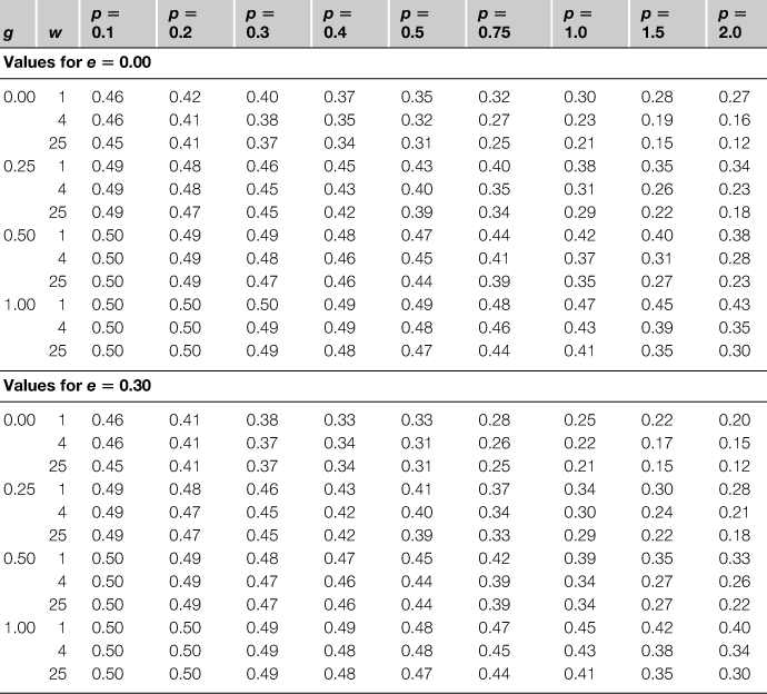
Reprinted from Utzinger and Klein (1979), with permission from Elsevier.
A monthly average value of Fw can be calculated by summing the beam radiation with and without shading over a month:
![]() (6.58)
(6.58)
Therefore, the mean monthly and area-average radiation on a shaded vertical window can be obtained by an equation similar to Eq. (2.107):
![]() (6.59)
(6.59)
Methods to estimate ![]() and
and ![]() are described in Section 2.3.8 in Chapter 2. An easy way to estimate
are described in Section 2.3.8 in Chapter 2. An easy way to estimate ![]() is by using Eq. (6.53) and finding the average of F for all sunshine hours for the recommended average day for each month, shown in Table 2.1.
is by using Eq. (6.53) and finding the average of F for all sunshine hours for the recommended average day for each month, shown in Table 2.1.
EXAMPLE 6.6
A window with height equal to 2 m and width equal to 8 m has an overhang with an extension equal to 0.5 m on both sides, gap 0.5 m, and the projection of 1.0 m. If Fw = 0.3, RB = 0.81, IB = 3.05 MJ/m2, ID = 0.45 MJ/m2, and ρG = 0.2, estimate area–average radiation received by the window.
Solution
First, the relative dimensions are estimated. Therefore,

From what was said previously, Fw–g = 0.5, and from Table 6.1, Fw–s = 0.40.
From Eq. (6.57),

6.2.6 Natural ventilation
One way of achieving comfort is by direct evaporation of sweat with air movement through ventilation openings. In many parts of the earth, in some months of the year, local cooling of a building can be achieved with natural ventilation. This is achieved by allowing air that is colder than the building to enter the building. Doing so removes some of the heat stored in the building. The reduction of cooling load varies from 40% to 90%. The lower number applies in warm, humid areas and the larger in mild or dry areas. Natural ventilation also has some disadvantages: safety, noise, and dust. Safety is not a considerable issue but it creates extra cost to protect the ventilation openings from unauthorized entry; noise is a problem when the building is located near a road, whereas dust is always a problem but is more pronounced if a building is located near a road or in open fields.
The main objective of natural ventilation is to cool the building and not its occupants. Opening areas that are about 10% of a building floor area can give about 30 air changes per hour, which can remove considerable quantities of heat from the building. In some cases, such as in office buildings, natural ventilation is used during the night when the office is closed to remove excess heat; thus, the building requires less energy to cool during the next morning. This is usually combined with thermal mass effects, as explained in Section 6.2.1, to shift the maximum heat dissipation from the walls and roof during the night, where it can be removed by natural ventilation and thus lower the cooling load during the day.
When designing a natural ventilation system, it is important to consider the way air flows around the building. Generally, as shown in Figure 6.8, wind creates a positive pressure on the windward side of the building, whereas on a side wall with respect to the windward side, the air creates a negative pressure, i.e., suction. A smaller amount of suction is also created on the leeward side of the building, due to eddies created from the wind. Therefore, an effective system is to allow openings in the windward and leeward sides, so as to create good cross-ventilation. It is usual to install insect screens to avoid having insects in the building. When these are used, they must be placed as far as possible from the window frame because they reduce the air flow by an amount equal to their blockage.
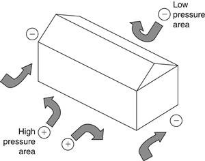
FIGURE 6.8 Pressure created because of the wind flow around a building.
It should be noted that the presence of windows on two walls does not guarantee good cross-ventilation unless there is a significant pressure difference. Additionally, buildings with windows on only one external wall are difficult to ventilate, even if the wind strikes directly on these windows. In this case, ventilation is facilitated by having the two windows as far apart as possible and using devices such as wing walls, which can be added to the building exterior with fixed or movable structures (see Figure 6.9). The objective of the wing wall is to cause one window to be in the positive pressure zone and the other in the negative.
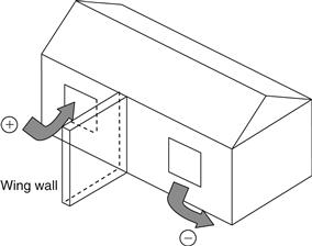
FIGURE 6.9 Use of a wing wall to help natural ventilation of windows located on the same side of the wall.
If the inlet window is located in the center of the wall, the incoming air jet will maintain its shape for a length that is approximately equal to the window size and then disperse completely. If, however, the inlet window is located near a side wall, the air stream attaches to the wall. A similar effect is obtained when the window is very close to the floor or ceiling. In warm areas, the objective is to direct the air flow toward the hot room surfaces (walls and ceiling) to cool them. The relative location of the outlet window, high or low, does not appreciably affect the amount of air flow. For better effects, it is preferable to allow outside air to mix with the room air; therefore, the outlet should be in such a location as to make the air change direction before leaving the room.
To create higher inlet velocity, the inlet window should be smaller than the outlet one, whereas the air flow is maximized by having equal areas for the inlet and outlet windows.
Leave a Reply