Two types of systems belong to this category: thermosiphon and the integrated collector storage systems. These are examined in the following sections.
5.1.1 Thermosiphon systems
Thermosiphon systems, shown schematically in Figure 5.1, heat potable water or transfer fluid and use natural convection to transport it from the collector to storage. The thermosiphoning effect occurs because the density of water drops with the increase of the temperature. Therefore, by the action of solar radiation absorbed, the water in the collector is heated and thus expands, becoming less dense, and rises through the collector into the top of the storage tank. There it is replaced by the cooler water that has sunk to the bottom of the tank, from which it flows down the collector. Circulation continues as long as the sun is shining. Since the driving force is only a small density difference, larger than normal pipe sizes must be used to minimize pipe friction. Connecting lines must also be well insulated to prevent heat loss and sloped to prevent formation of air pockets, which would stop circulation.
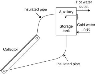
FIGURE 5.1 Schematic diagram of a thermosiphon solar water heater.
The advantages of thermosiphon systems are that they do not rely on pumps and controllers, are more reliable, and have a longer life than forced circulation systems. Moreover, they do not require an electrical supply to operate and they naturally modulate the circulation flow rate in phase with the radiation levels.
The main disadvantage of thermosiphon systems is that because the storage tank should be above the collector they are comparatively tall units, which makes them not very attractive aesthetically. The two types of thermosiphon systems are pressurized and unpressurized. In pressurized thermosiphon units, the make-up water is from city mains or pressure units and the collectors and storage tanks must be able to withstand the working pressure. When the city water is used directly, pressure-reducing and relief valves must be installed to protect the system because the pressure can be greater than the working pressure of the collectors and storage tank. In gravity systems—usually installed where the city water supply is intermittent—a cold water storage tank is installed on top of the solar collector, supplying both the hot water cylinder and the cold water needs of the house. This makes the collector unit taller and less attractive.
Another disadvantage of the system is related to the quality of the water used. As the system is open, extremely hard or acidic water can cause scale deposits that clog or corrode the absorber fluid passages.
Typical collector configurations include flat plate, shown in Figure 5.2(a), and evacuated tube collectors, shown in Figure 5.2(b).
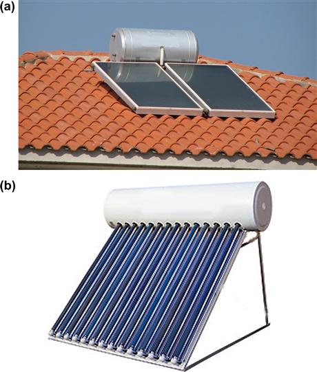
FIGURE 5.2 Thermosiphon system configurations. (a) Flat-plate collector configuration. (b) Evacuated tube collector configuration.
Thermosiphon systems can be built with freeze protection devices, ranging from dump valves or heaters in the bottom of the collector header for mild freeze areas to inherent freeze resistance by using a natural circulation antifreeze closed loop between the collector and the tank (Morrison, 2001).
Theoretical performance of thermosiphon solar water heaters
The performance of thermosiphon solar water heaters has been studied extensively, both experimentally and analytically, by numerous researchers. Among the first studies were those of Close (1962) and Gupta and Garg (1968), who developed one of the first models for the thermal performance of a natural circulation solar water heater with no load. They represented solar radiation and ambient temperature by Fourier series and were able to predict a day’s performance in a manner that agreed substantially with experiments.
Ong performed two studies (1974; 1976) to evaluate the thermal performance of a solar water heater. He instrumented a relatively small system with five thermocouples on the bottom surface of the water tubes and six thermocouples on the bottom surface of the collector plate. A total of six thermocouples were inserted into the storage tank and a dye tracer mass flowmeter was employed. Ong’s studies appear to be the first detailed ones on a thermosiphonic system.
Morrison and Braun (1985) studied the modeling and operation characteristics of thermosiphon solar water heaters with vertical or horizontal storage tanks. They found that the system performance is maximized when the daily collector volume flow is approximately equal to the daily load flow, and the system with a horizontal tank did not perform as well as that with a vertical one. This model has also been adopted by the TRNSYS simulation program (see Chapter 11, Section 11.5.1). According to this model, a thermosiphon system consisting of a flat-plate collector and a stratified tank is assumed to operate at a steady state. The system is divided into N segments normal to the flow direction, and the Bernoulli’s equation for incompressible flow is applied to each segment. For steady-state conditions the sum of pressure drop at any segment is:
And the sum of the pressure changes around the loop is 0; that is,
![]() (5.1b)
(5.1b)
ρi = density of any node calculated as a function of local temperature (kg/m3);
hfi = friction head drop through an element (m); and
Hi = vertical height of the element (m).
For each time interval the thermosiphon flow rate must uniquely satisfy Eq. (5.1b).
The collector thermal performance can be modeled by dividing it into Nc equally sized nodes. The temperature at the midpoint of any collector mode k is given by:
![]() (5.2)
(5.2)
![]() = thermosiphonic flow rate (kg/s);
= thermosiphonic flow rate (kg/s);
The collector parameter, F′UL, is calculated from the collector test data for FRUL at test flow rate ![]() by Eq. (4.18), which using the new symbol for test flow rate is:
by Eq. (4.18), which using the new symbol for test flow rate is:
![]() (5.3)
(5.3)
Finally, the useful energy from the collector is obtained from:
![]() (5.4a)
(5.4a)
Where the ratio r from Eq. (4.17a) becomes:
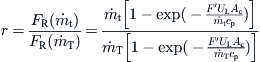 (5.4b)
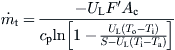
The temperature drop along the collector inlet and outlet pipes is usually very small (short distance, insulated pipes), and the pipes are considered to be single nodes, with negligible thermal capacitance. The first-law analysis gives the following expressions for the outlet temperature (Tpo) of pipes:
![]() (5.5)
(5.5)
The friction head loss in pipes is given by:
![]() (5.6)
(5.6)
k = fitting loss coefficient; and
The friction factor, f, is equal to:
![]() (5.7a)
(5.7a)
![]() (5.7b)
(5.7b)
The fitting loss coefficient for various parts of the circuit can be estimated by using the data given in Table 5.2.
Table 5.2
Fitting Loss Coefficient for Various Parts of the Thermosiphon Circuit
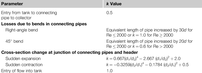
Note: For pipe diameters, d1 = inlet diameter and d2 = outlet diameter.
The friction factor for the developing flow in the connecting pipes and collector risers is given by:
![]() (5.7c)
(5.7c)
The collector header pressure drop, Ph, is equal to the average of pressure change along inlet and outlet headers for equal mass flow in each riser, N, given by:
![]() (5.8b)
(5.8b)
![]() (5.9)
(5.9)
where, from Eq. (5.7a), f = 64/Re (Re based on inlet header velocity and temperature) and
![]() (5.10)
(5.10)
Based on the outlet header velocity and temperature,
![]() (5.11)
(5.11)
Finally,
![]() (5.12)
(5.12)
To model the complete system, the interaction of the storage tank is required. This is modeled with the fully stratified storage tank model, which is presented in Section 5.3.3.
The procedure to model the complete system is as follows. Initially, the temperature distribution around the thermosiphon loop for the flow rate of the previous time step is evaluated. The inlet temperature to the collector is computed from the bulk mean temperature of the segments in the bottom of the tank with a volume equal to the collector volume flow (see Section 5.3.3). After allowance for heat loss from the inlet pipe, with Eq. (5.6), is made, the temperature of each of the Nc fixed nodes used to represent the collector temperature profile is evaluated from Eq. (5.2). Finally, the temperature of the new fluid segment returned to the tank is computed from the collector outlet temperature and the temperature drop across the return pipe to the tank. A new tank temperature profile is then evaluated (see Section 5.3.3).
The thermosiphon pressure head due to density differences around the loop is determined from the system temperature profile. The difference between the friction pressure drop around the circuit and the net thermosiphon pressure is evaluated for this flow rate. These values and those from the previous calculation, for the flow rate and net difference between the friction and static pressures, are then used to estimate the new flow; this process is repeated until Eq. (5.1b) is satisfied. This procedure is not suitable for hand calculations, but it is relatively easy to do with a computer.
A simple way to estimate the flow rate that will be created in a thermosiphon solar water heater is to assume that there is a constant temperature increase of water flowing through the collector and estimate the flow rate that will create this temperature difference for the estimated collector gain. Considering the basic collector performance Eq. (3.60) and using the concept of absorbed solar radiation:
![]() (5.13)
(5.13)
Solving for the flow rate we get:
![]() (5.14)
(5.14)
By assuming that the collector efficiency factor F′ is independent of flow rate, substituting Eq. (3.58) for FR and rearranging gives:
 (5.15)
The obtained value of flow rate can then be used to estimate F′ and if there is a difference a second iteration is made.
Close (1962) compared computed and experimental temperature differences in Australian-type collector systems and found that there exists a temperature difference of 10 °C when these are well designed and without serious flow restrictions.
More details on the thermosiphon head are given in Chapter 11, Section 11.1.4.
Reverse circulation in thermosiphon systems
At night or whenever the collector is cooler than the water in the tank, the direction of the thermosiphon flow reverses, thus cooling the stored water. It should be noted that thermosiphon collector loop circulation is driven by thermal stratification in the collector loop and the section of the tank below the collector flow return level. The major problem in thermosiphon system design is to minimize a heat loss due to reverse thermosiphon circulation at night, when the sky temperature is low. Norton and Probert (1983) recommend that, to avoid reverse flow, the tank-to-collector separation distance should be between 200 and 2000 mm. A practical way to prevent a reverse flow is to place the top of the collector about 300 mm below the bottom of the storage tank.
Nighttime heat loss from a collector is a function of an ambient air temperature and sky temperature. If the sky temperature is significantly below the ambient temperature, cooling of the collector will cause fluid to thermosiphon in the reverse direction through the collector, and the fluid may be cooled below the ambient temperature. When the reverse flow enters the return pipe to the bottom of the tank, it is mixed with the warmer water contained in the storage tank. The combination of cooling below the ambient temperature in the collector and heating in the return pipe causes reverse flow in all thermosiphon configurations, irrespective of the vertical separation between the top of the collector and the bottom of the tank (Morrison, 2001).
Vertical versus horizontal tank configurations
Because the operation of the thermosiphon system depends on the stratification of the water in the storage tank, vertical tanks are more effective. It is also preferable to have the auxiliary heater as high as possible in the storage tank, as shown in Figure 5.1, to heat only the top of the tank with auxiliary energy when this is needed. This is important for three reasons:
1. It improves stratification.
2. Tank heat losses are increased linearly with the storage temperature.
3. As shown in Chapter 4, the collector operates at higher efficiency at a lower collector inlet temperature.
To reduce the overall height of the unit, however, horizontal tanks are frequently used. The performance of horizontal tank thermosiphon systems is influenced by the conduction between the high-temperature auxiliary zone in the top of the tank and the solar zone and by mixing of the flow injection points (Morrison and Braun, 1985). The performance of these systems can be improved by using separate solar and auxiliary tanks or by separating the auxiliary and preheat zones with an insulated baffle, as shown in Figure 5.3. A disadvantage of the two tank systems or segmented tanks is that the solar input cannot heat the auxiliary zone until there is a demand.
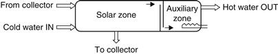
FIGURE 5.3 Configuration of a segmented tank with an insulating baffle.
Thermal stratification in shallow horizontal tanks also depends on the degree of mixing at the load, make-up water, and collector inlets to the tank. The load should be drawn from the highest possible point, whereas the make-up water flow should enter the tank through a distribution pipe or a diffuser so that it is introduced into the bottom of the tank without disturbing the temperature stratification or mixing the top auxiliary zone with the solar zone. The collector return flow to the tank also should enter through a flow distributor so that it can move to its thermal equilibrium position without mixing with intermediary fluid layers. Because the collector return is usually hot, many manufacturers make a small bend at the inlet pipe, facing upward.
Generally, the penalty associated with horizontal tanks is that the shallow tank depth degrades stratification because of conduction through the walls of the tank and water. Additionally, for in-tank auxiliary systems conduction between the auxiliary and solar zones influences the solar performance. For horizontal tanks with diameters greater than 500 mm, there is only a relatively small performance loss relative to a vertical tank, and the above effects increase significantly for smaller tank diameters (Morrison, 2001).
Freeze protection
For locations that have a mild climate, the open loop thermosiphon solar water heater is the most widely used system. With freeze protection, thermosiphon systems can also be used in locations that experience minor freeze conditions. This can be provided by water dump valves, electric heating in the collector header, or tapered riser tubes to control ice growth in the riser so that a rigid and expanding ice plug is avoided (Xinian et al., 1994). All these techniques have been used successfully by solar water heater manufacturers, and their suitability is proven in areas with mild freeze conditions. They are not suitable, though, in areas with hard freezing. In such cases, the only suitable design is the use of antifreeze collector loops with a heat exchanger between the collector and the tank and an antifreeze heat transfer fluid circulating in the collector and the heat exchanger. For horizontal tank configuration, the most widely adopted system is the mantle or annular heat exchanger concept, shown in Figure 5.4.
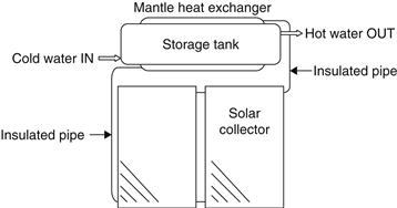
FIGURE 5.4 Mantle heat exchanger concept.
Mantle heat exchanger tanks are easy to construct and provide a large heat transfer area. Mantle heat exchangers are also used in vertical tanks and forced circulation systems, as can be seen in Section 5.2.2. Manufacturers of horizontal tanks usually use as large a mantle as possible, covering almost the full circumference and full length of the storage tank. The usual heat transfer fluid employed in these systems is a water–ethylene glycol solution.
Tracking thermosiphons
The possibility of having either a movable thermosiphon solar water heater or a heater where only the inclination could be moved seasonally was investigated by the author and collaborators (Michaelides et al., 1999). The increased performance of the system was compared to the added cost to achieve the movement of the heaters, and it was found that even the simplest seasonal change of the collector inclination is not cost-effective compared to the traditional fixed system.
5.1.2 Integrated collector storage systems
Integrated collector storage (ICS) systems use the hot water storage as part of the collector, i.e., the surface of the storage tank is used as the collector absorber. As in other systems, to improve stratification, the hot water is drawn from the top of the tank and cold make-up water enters the bottom of the tank on the opposite side. Usually, the storage tank surface is selectively coated to avoid heat loss.
The main disadvantage of the ICS systems is the high thermal losses from the storage tank to the surroundings, since most of the surface area of the storage tank cannot be thermally insulated, because it is intentionally exposed to be able to absorb solar radiation. In particular, the thermal losses are greatest during the night and overcast days with low ambient temperatures. Due to these losses, the water temperature drops substantially during nighttime, especially during the winter. Various techniques have been used to keep this from happening. Tripanagnostopoulos et al. (2002) present a number of experimental units in which a reduction in thermal losses was achieved by considering single and double cylindrical horizontal tanks properly placed in truncated symmetric and asymmetric CPC reflector troughs. Alternatively, if a 24 h hot water supply is required, these systems can be used only for preheating and, in such a case, must be connected in series with a conventional water heater.
Details of an ICS unit developed by the author are presented here (Kalogirou, 1997). The system employs a non-imaging CPC cusp-type collector. A fully developed cusp concentrator for a cylindrical receiver is shown in Figure 5.5. The particular curve illustrated has an acceptance half angle, θc, of 60° or a full acceptance angle, 2θc, of 120°. Each side of the cusp has two mathematically distinct segments, smoothly joined at a point P related to θc. The first segment, from the bottom of the receiver to point P, is the involute of the receiver’s circular cross-section. The second segment is from point P to the top of the curve, where the curve becomes parallel to the y-axis (McIntire, 1979).
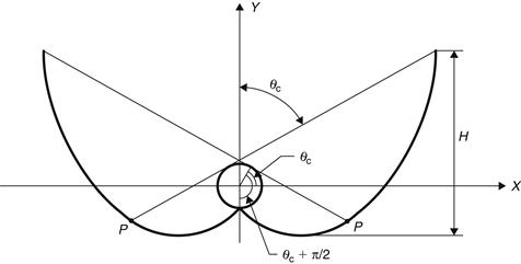
FIGURE 5.5 Fully developed cusp.
With reference to Figure 5.6, for a cylindrical receiver, the radius, R, and the acceptance half angle, θc, the distance, ρ, along a tangent from the receiver to the curve, are related to the angle θ between the radius to the bottom of the receiver and the radius to the point of tangency, T, by the following expressions for the two sections of the curve (McIntire, 1979):
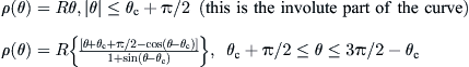 (5.16)
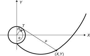
FIGURE 5.6 Mirror coordinates for ideal non-imaging cusp concentrator.
The two expressions for ρ(θ) are equivalent for the point P in Figure 5.5, where θ = θc + π/2. The curve is generated by incrementing θ in radians, calculating ρ, then calculating the coordinates, X and Y, by:
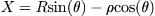
![]() (5.17)
(5.17)
Figure 5.5 shows a full, untruncated curve, which is the mathematical solution for a reflector shape with the maximum possible concentration ratio. The reflector shape shown in Figure 5.5 is not the most practical design for a cost-effective concentrator because reflective material is not effectively used in the upper portion of the concentrator. As in the case of the compound parabolic collector, a theoretical cusp curve should be truncated to a lower height and slightly smaller concentration ratio. Graphically, this is done by drawing a horizontal line across the cusp at a selected height and discarding the part of the curve above the line. Mathematically, the curve is defined to a maximum angle θ value less than 3π/2 − θc. The shape of the curve below the cutoff line is not changed by truncation, so the acceptance angle used for the construction of the curve, using Eq. (5.16), of a truncated cusp is equal to the acceptance angle of the fully developed cusp from which it was truncated.
A large acceptance angle of 75° is used in this design so the collector can collect as much diffuse radiation as possible (Kalogirou, 1997). The fully developed cusp, together with the truncated one, is shown in Figure 5.7. The receiver radius considered in the construction of the cusp is 0.24 m. The actual cylinder used, though, is only 0.20 m. This is done in order to create a gap at the underside of the receiver and the edge of the cusp in order to minimize the optical and conduction losses.
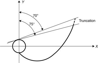
FIGURE 5.7 Truncation of non-imaging concentrator.
The final design is shown in Figure 5.8. The collector aperture is 1.77 m2, which, in combination with the absorber diameter used, gives a concentration ratio of 1.47 (Kalogirou, 1997). It should be noted that, as shown in Figure 5.8, the system is inclined at the local latitude in order to work effectively.
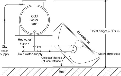
FIGURE 5.8 The complete solar ICS hot water system.
Another possibility considered to reduce the night thermal losses for the design shown in Figure 5.8, in view of the findings of Eames and Norton (1995) on the use of baffles to reduce convection currents flowing across the glazing that increase the thermal losses, is the insertion of a second cylinder of smaller diameter in the space between the main cylinder and the glass cover and using a small piece of insulation at the point of contact between the two cylinders and between the secondary cylinder and the glass cover as shown in Figure 5.8 with a dotted line. This modification offers a number of advantages: storage capacity increased by 30%; top cylinder provides some sort of insulation (for radiation heat loss) as the main cylinder does not see the sky directly; the top cylinder creates a restriction to the flow of the convection currents (just like the baffle does); and finally, the secondary cylinder is used as a preheating for the main one and thus the draw-off characteristics of the whole unit improved considerably, as the cold make-up water does not enter into the main cylinder directly. The extra cylinder increased the cost of the ICS system by 8%, whereas the performance of the system increased by about 7% (Kalogirou, 1998).
Leave a Reply