
As we have seen in Chapter 3, the materials used for the construction of the collector should be able to withstand, in addition to the effects created because of the circulating fluid (corrosion, scale deposits, etc.), the adverse effects of the sun’s ultraviolet radiation, and the collector should have an operation life of more than 20 years. Solar collectors are also required to withstand cyclic thermal operation many times a day and extreme operating conditions, such as freezing, overheating, thermal shocks, external impact due to hail or vandalism, and pressure fluctuations. Most of these factors occur simultaneously.
It is therefore required to perform tests on solar collectors to determine their quality. In particular, the ability of a collector to resist extreme operating conditions is examined as specified in International Standard ISO 9806-2:1995 (1995a). This standard applies to all types of solar collectors, including integral collector storage systems, except tracking concentrating collectors. Collectors are required to resist a number of influences, which can be clearly identified and quantified, such as high internal fluid pressures, high temperatures, and rain penetration, as shown in Table 4.5. The tests are required to be applied in the sequence specified in Table 4.5 so that possible degradation in one test will be exposed in a later test.
Table 4.5
Sequence of Quality Tests for Solar Collectors
| Sequence | Test | Collector |
| 1 | Internal pressure | A |
| 2 | High-temperature resistancea | A |
| 3 | Exposure | A, B, and C |
| 4 | External thermal shockb | A |
| 5 | Internal thermal shock | A |
| 6 | Rain penetration | A |
| 7 | Freeze resistance | A |
| 8 | Internal pressure (retest) | A |
| 9 | Thermal performance | A |
| 10 | Impact resistance | A or B |
| 11 | Final inspection | A, B, and C |
aFor organic absorbers, the high-temperature resistance test should be performed first, to determine the collector stagnation temperature needed for the internal pressure test.
bThe external thermal shock test may be combined with the exposure test.
For many quality tests, the collector is required to operate at the stagnation temperature. Provided that the collector was tested at a sufficiently high inlet water temperature, the performance equation can be used to determine stagnation temperature. By using Eq. (4.11) and denoting FR(τα)n as ηo,
![]() (4.52)
(4.52)
Internal pressure test
The absorber is pressure tested to assess the extent to which it can withstand the pressures it might meet in service. For the metallic absorbers, the test pressure, maintained for 10 min, is either the maximum test pressure specified by the manufacturer or 1.5 times the maximum collector operating pressure stated by the manufacturer, whichever is lower.
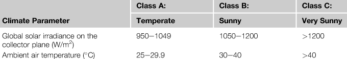
For absorbers made of organic materials (plastics or elastomers), the test temperature is the maximum temperature the absorber will reach under stagnation conditions. This is because the properties of organic materials are temperature dependent. One of the alternative sets of reference conditions given in Table 4.6 must be used to determine the test temperature, depending on the climate in which the collector will be used. The test pressure should be 1.5 times the maximum collector operating pressure specified by the manufacturer and should be maintained for at least 1 h.
Table 4.6
Climatic Reference Conditions for the High-Temperature Resistance Test
For air-heating collectors, the test pressure is 1.2 times the maximum collector operating pressure difference above or below atmospheric pressure, as specified by the manufacturer, maintained for 10 min.
High-temperature resistance test
This test is intended to assess rapidly whether a collector can withstand high irradiance levels without failures such as glass breakage, collapse of plastic cover, melting of plastic absorber, or significant deposits on the collector cover from out-gassing of the collector material. The test is performed at a temperature equal to the collector stagnation temperature. The test is performed for a minimum of 1 h after a steady state is reached. The conditions required in this test are as shown in Table 4.6 with the addition of surrounding air speed, which must be less than 1 m/s.
Exposure test
The exposure test provides a low-cost indication of the aging effects that are likely to occur during a longer period of natural aging. In addition, it allows the collector to “settle”, such that subsequent qualification tests are more likely to give repeatable results. An empty collector is mounted outdoors and all of its fluid pipes are sealed to prevent cooling by natural circulation of air except one pipe, which is left open to permit free expansion of air in the absorber. One of the alternative sets of reference conditions given in Table 4.7 must be used, depending on the climate in which the collector will operate. For each class of reference conditions, the collector is exposed until at least 30 days (which need not be consecutive) have passed with the minimum irradiation shown in Table 4.7.
Table 4.7
Climate Reference Conditions for Exposure Test as well as for External and Internal Thermal Shock Tests
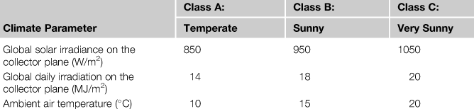
Note: Values given are minimums for testing.
External thermal shock test
Collectors from time to time may be exposed to sudden rainstorms on hot sunny days, causing a severe external thermal shock. This test is intended to assess the capability of a collector to withstand such thermal shocks without a failure. An empty collector is used here, as in previous tests prepared in the same way. An array of water jets is arranged to provide a uniform spray of water over the collector. The collector is maintained in steady-state operating conditions under a high level of solar irradiance for a period of 1 h before the water spray is turned on. It is then cooled by the water spray for 15 min before being inspected. Here again, one of the alternative sets of reference conditions given in Table 4.7 can be used, depending on the climate in which the collector will operate, and the heat transfer fluid must have a temperature of less than 25 °C.
Internal thermal shock test
Collectors from time to time may be exposed to a sudden intake of cold heat transfer fluid on hot sunny days, causing a severe internal thermal shock. This could happen, for example, after a period of shutdown, when the installation is brought back into operation while the collector is at its stagnation temperature. This test is intended to assess the capability of a collector to withstand such thermal shocks without failure. Here again, an empty collector is used, as in previous tests prepared in the same way; the same reference conditions given in Table 4.7 can be used, depending on the climate in which the collector will operate, and the heat transfer fluid must have a temperature of less than 25 °C.
Rain penetration
This test is intended to assess the extent to which collectors are substantially resistant to rain penetration. The collectors must not normally permit the entry of either free-falling rain or driving rain, either through the glazing seals or from ventilation holes or drain holes. For this test, the inlet and outlet fluid pipes of the collector must be sealed, and the collector must be placed in a test rig at the shallowest angle to the horizontal recommended by the manufacturer. If this angle is not specified, then the collector can be placed at a tilt of 45° to the horizontal or less. Collectors designed to be integrated into a roof structure must be mounted on a simulated roof and have their underside protected. Other collectors must be mounted in a conventional manner on an open frame. The collector must be sprayed on all sides using spray nozzles or showers for a test period of 4 h.
For collectors that can be weighed, weighing must be done before and after the test. After the test, external surfaces of the collector must be wiped dry before the weighing. During the wiping, transport, and placement on the weighing machine, the angle of inclination of the collector must not be changed appreciably. For collectors that cannot be weighed, the penetration of water into the collector can be determined only by visual inspection.
Freezing test
This test is intended to assess the extent to which water-heating collectors that are claimed to be freeze resistant can withstand freezing and freeze-thaw cycles. This test is not intended for use with collectors that are filled with antifreeze fluids. Two test procedures are specified: one for collectors claimed to be freeze resistant when filled with water and one for collectors claimed to resist freezing after being drained.
For collectors claimed to be able to withstand freezing, the collector is mounted in a cold chamber. The collector must be inclined at the shallowest angle to the horizontal recommended by the manufacturer. If no angle is specified by the manufacturer, then the collector must be inclined at an angle of 30° to the horizontal. Unglazed collectors must be tested in a horizontal position, unless this is excluded by the manufacturer. Next, the collector is filled with water at the operating pressure. The cold chamber temperature is cycled, and at the end of each cycle, the collector is refilled with water at operating pressure.
For collectors claimed to resist freezing after being drained (i.e., they employ a drain down system to protect them from freezing), the collector is mounted in a cold chamber as before with the same provisions for the collector inclination. The collector is next filled with water, kept at operating pressure for 10 min, then drained using the device installed by the manufacturer. The contents of the absorber are maintained at −20 ± 2 °C for at least 30 min during the freezing part of the cycle and raised to above 10 °C during the thawing part of the cycle, which is again of minimum 30 min duration. The collector must be subjected to three freeze-thaw cycles.
Impact resistance test
This is an optional test intended to assess the extent to which a collector can withstand the effects of heavy impacts, such as those caused by minor vandalism or likely to occur during installation. Heavy impacts may also be caused by hailstones.
The collector is mounted either vertically or horizontally on a stiff support that must have a negligible distortion or deflection at the time of impact. Steel balls with a mass of 150 g are used to simulate the heavy impact. If the collector is mounted horizontally, then the steel balls are dropped vertically; if it is mounted vertically, then the impacts are directed horizontally by means of a pendulum.
The point of impact must be no more than 5 cm from the edge of the collector cover and no more than 10 cm from the corner of the collector cover and must be moved by several millimeters each time the steel ball is dropped. A steel ball must be dropped onto the collector 10 times from the first test height, then 10 times from the second test height, and so forth until the maximum test height is reached. The test is stopped when the collector exhibits some damage or has survived the impact of 10 steel balls at the maximum test height. The test heights start from 0.4 up to 2.0 m in steps of 20 cm.
In addition to the preceding quality tests, the ISO developed a range of material and product quality test standards for solar collectors. The following specific material test methods standards have been developed:
• ISO 9553:1997. Solar energy—Methods of testing preformed rubber seals and sealing compounds used in collectors.
• ISO 9808:1990. Solar water heaters—Elastomeric materials for absorbers, connecting pipes, and fittings—Methods of assessment.
• ISO/TR 10217:1989. Solar Energy—Water heating systems—Guide to material selection with regard to internal corrosion.
Leave a Reply