
Solar chemistry applications include a variety of fields; the main ones are the production of energy carriers (e.g. hydrogen), also called reforming of fuels; fuel cells; materials processing and detoxification; and recycling of waste materials. These are examined in this section.
7.3.1 Reforming of fuels
Solar energy is essentially unlimited and its utilization does not create ecological problems. However, solar radiation reaching the earth is intermittent and not distributed evenly. There is thus a need to collect and store solar energy and transport it from the sunny uninhabited regions, such as deserts, to industrialized populated regions, where great quantities of energy are needed. An effective way to achieve this process is by the thermochemical conversion of solar energy into chemical fuels. This method provides a thermochemically efficient path for storage and transportation. For this purpose, high-concentration-ratio collectors, similar to the ones used for power generation (see Chapter 10), are required. By concentrating solar radiation in receivers and reactors, one can supply energy to high-temperature processes to drive endothermic reactions.
Hydrogen is the main fuel (energy carrier) used in fuel cells (see next section). Today, however, no sources of hydrogen with a widespread delivery infrastructure are readily available. This issue can be solved by using fossil fuels to generate the hydrogen required. The transformation of a fossil fuel to hydrogen is generally called fuel reforming. Steam reforming is one example, in which steam is mixed with the fossil fuel at temperatures around 760 °C. This high temperature can be obtained by burning conventional fuels or by high-concentration concentrating solar collectors. The chemical equation of this reforming reaction for natural gas composed primarily of methane (CH4) is:
![]() (7.1)
(7.1)
Fuel reforming can be done in facilities of different sizes. It can be done in a central facility such as a chemical plant at a large scale. Such a plant produces pure hydrogen, which can be a high-pressure gas or liquid. Fuel reforming can also be performed on an intermediate scale in various facilities such as a gasoline station. In this case, refined gasoline or diesel fuel would be required, which can be delivered to the station with its current infrastructure. On-site equipment would then reform the fossil fuel into a mixture composed primarily of hydrogen and other molecular components, such as CO2 and N2. This hydrogen would most probably be delivered to customers as a high-pressure gas.
The fuel-reforming process can also be performed on a small scale, according to the requirements, immediately before its introduction into the fuel cell. For example, a fuel cell-powered vehicle can have a gasoline tank, which would use the existing infrastructure of gasoline delivery, and an onboard fuel processor, which would reform the gasoline into a hydrogen-rich stream that would be fed directly to the fuel cell.
In the future, it is anticipated that most of the hydrogen required to power fuel cells could be generated from renewable sources, such as wind or solar energy. For example, the electricity generated at a wind farm or with photovoltaics could be used to split water into hydrogen and oxygen through electrolysis. Electrolysis as a process could produce pure hydrogen and pure oxygen. The hydrogen thus produced could then be delivered by pipeline to the end users.
Chemistry applications include also the solar reforming of low-hydrocarbon fuels such as LPG and natural gas and upgrading them into a synthetic gas that can be used in gas turbines. Thus, weak gas resources diluted with carbon dioxide can be used directly as feed components for the conversion process. Therefore, natural gas fields currently not exploited due to high CO2 content might be opened to the market. Furthermore, gasification products of unconventional fuels, such as biomass, oil shale, and waste asphaltenes, can also be fed into the solar upgrade process (Grasse, 1998).
A model for solar volumetric reactors for hydrocarbon-reforming operations at high temperature and pressure is presented by Yehesket et al. (2000). The system is based on two achievements; the development of a volumetric receiver tested at 5000–10,000 suns, gas outlet temperature of 1200 °C, and pressure at 20 atm and a laboratory-scale chemical kinetics study of hydrocarbon reforming. Other related applications are a solar-driven ammonia-based thermochemical energy storage system (Lovegrove et al., 1999) and an ammonia synthesis reactor for a solar thermochemical energy storage system (Kreetz and Lovegrove, 1999).
Another interesting application is solar zinc and syngas production, both of which are very valuable commodities. Zinc finds application in zinc–air fuel cells (ZAFC) and batteries. Zinc can also react with water to form hydrogen, which can be further processed to generate heat and electricity. Syngas can be used to fuel highly efficient combined cycles or as the building block of a wide variety of synthetic fuels, including methanol, which is a very promising substitute for gasoline to fuel cars (Grasse, 1998).
7.3.2 Fuel cells
A fuel cell is an electrochemical device that converts the chemical energy of a fuel, such as hydrogen, natural gas, methanol, or gasoline, and an oxidant, such as air or oxygen, into electricity. Electrochemical devices generate electricity without combustion of the fuel and oxidizer, as opposed to what occurs with traditional methods of electricity generation. In principle, a fuel cell operates like a battery, but unlike a battery, it does not run down or require recharging. In fact, a fuel cell produces electricity and heat as long as fuel and an oxidizer are supplied. A fuel cell, like a battery, has a positively charged anode, a negatively charged cathode, and an ion-conducting material, called an electrolyte. The main fuel used in fuel cells is hydrogen. An introduction to hydrogen production and use is given in Chapter 1.
An electrochemical reaction is a reaction in which one species, the reducing agent, is oxidized (loses electrons) and another species, the oxidizing agent, is reduced (gains electrons).
The direct conversion of chemical energy to electrical energy is more efficient and generates much fewer pollutants than traditional methods that rely on combustion. Therefore, fuel cells can generate more electricity from the same amount of fuel. Furthermore, by avoiding the combustion process that occurs in traditional power-generating methods, the generation of pollutants during the combustion process is minimized. Some of the pollutants that are significantly lower for fuel cells are oxides of nitrogen and unburned hydrocarbons and carbon monoxide, which is a poisonous gas.
Basic characteristics
Fuel cell construction generally consists of a fuel electrode (anode) and an oxidant electrode (cathode) separated by an ion-conducting membrane. In the basic fuel cell, oxygen passes over one electrode and hydrogen over the other; in doing so, it generates electricity, water, and heat. Fuel cells chemically combine the molecules of a fuel and oxidizer without burning or having to dispense with the inefficiencies and pollution of traditional combustion.
Some other important characteristics of fuel cells are as follows:
• Charge carrier. The charge carrier is the ion that passes through the electrolyte. The charge carrier differs among different types of fuel cells. For most types of fuel cells, however, the charge carrier is a hydrogen ion, H+, which has a single proton.
• Contamination. Fuel cells can be contaminated by different types of molecules. Such a contamination can lead to severe degradation in their performance. Because of the difference in electrolyte, catalyst, operating temperature, and other factors, different molecules can behave differently in various fuel cells. The major contamination agent for all types of fuel cells is sulfur-containing compounds, such as hydrogen sulfide (H2S) and carbonyl sulfide (COS).
• Fuels. Hydrogen is currently the most popular fuel for fuel cells. Some gases, such as CO and CH4, have different effects on fuel cells, depending on the type of fuel cell. For example, CO is a contaminant to fuel cells operating at relatively low temperatures, such as the proton exchange membrane fuel cell (PEMFC). However, CO can be used directly as a fuel for the high-temperature fuel cells, such as the solid oxide fuel cell (SOFC).
• Performance factors. The performance of a fuel cell depends on numerous factors, such as the electrolyte composition, the geometry of the fuel cell, the operating temperature, and gas pressure. The geometry of the fuel cell is affected mainly by the surface area of the anode and cathode.
A valuable source that covers highly technical information on different types of fuel cells is the Fuel Cell Handbook published by the U.S. Department of Energy. It is freely available on the Internet (U.S. Department of Energy, 2000) or from the fuel cell test and evaluation center of the U.S. Ministry of Defense (FCTec, 2008).
Fuel cell chemistry
Fuel cells generate electricity from a simple electrochemical reaction in which an oxidizer, typically oxygen from air, and a fuel, typically hydrogen, combine to form a product, which for the typical fuel cell is water. The basic principle of fuel cell operation is that it separates the oxidation and reduction into separate compartments, which are the anode and the cathode (separated by a membrane), thereby forcing the electrons exchanged between the two half reactions to travel through the load. Oxygen (air) continuously passes over the cathode and hydrogen passes over the anode to generate electricity, while the by-products are heat and water. The fuel cell itself has no moving parts, so it is a quiet and reliable source of power. A schematic representation of a fuel cell with the reactant–product gases and the ion conduction flow directions through the cell is shown in Figure 7.9. The basic physical structure or building block of a fuel cell consists of an electrolyte layer in contact with a porous anode and cathode on either side.

FIGURE 7.9 Schematic diagram of a fuel cell.
Figure 7.9 is a simplified diagram that demonstrates how the fuel cell works. In a typical fuel cell, gaseous fuels are fed continuously to the anode (negative electrode) compartment and an oxidant (i.e., oxygen from air) is fed continuously to the cathode (positive electrode) compartment. At electrodes, the electrochemical reactions take place and produce an electric current. The fuel cell is an energy conversion device that theoretically has the capability of producing electrical energy for as long as the fuel and oxidant are supplied to the electrodes. In reality, degradation, primarily corrosion, or malfunction of components limits the practical operating life of fuel cells (U.S. Department of Energy, 2000).
The electrolyte that separates the anode and cathode is an ion-conducting material. At the anode, hydrogen and its electrons are separated so that the hydrogen ions (protons) pass through the electrolyte while the electrons pass through an external electrical circuit as a direct current (DC) that can power useful devices, usually through an inverter, which converts the DC current into an AC one. The hydrogen ions combine with the oxygen at the cathode and are recombined with the electrons to form water. The reactions taking place in a fuel cell are as follows.
Anode half reaction (oxidation),
![]() (7.2)
(7.2)
Cathode half reaction (reduction),
![]() (7.3)
(7.3)
Overall cell reaction,
![]() (7.4)
(7.4)
To obtain the required power, individual fuel cells are combined into fuel cell stacks. The number of fuel cells in the stack determines the total voltage, and the surface area of each cell determines the total current (FCTec, 2008). Multiplying the voltage by the current yields the total electrical power generated as:
![]() (7.5)
(7.5)
Porous electrodes, mentioned previously, are crucial for good electrode performance. Porous electrodes, used in fuel cells, achieve very high current densities, which are possible because the electrode has a high surface area relative to the geometric plate area, which significantly increases the number of reaction sites; and the optimized electrode structure has favorable mass transport properties. In an idealized porous gas fuel cell electrode, high current densities at reasonable polarization are obtained when the liquid (electrolyte) layer on the electrode surface is sufficiently thin, so that it does not significantly impede the transport of reactants to the electroactive sites and a stable three-phase (gas–electrolyte–electrode surface) interface is established (U.S. Department of Energy, 2000).
Types of fuel cells
Fuel cells are classified by their electrolyte material. Today, several types of fuel cells have been developed for applications ranging in size from a mobile phone (with under 1 W power) to a small power plant for an industrial facility or a small town (in the megawatt range). The main types of fuel cells that exist today are the following:
Alkaline fuel cell (AFC)
Alkaline fuel cells (AFCs) are one of the most developed technologies and have been used since the mid-1960s by NASA in the Apollo and space shuttle programs. The fuel cells on board these spacecraft provide electrical power for onboard systems, as well as drinking water. A schematic diagram of an AFC is shown in Figure 7.10. AFCs are among the most efficient (nearly 70%) in generating electricity. The electrolyte in this fuel cell is an aqueous (water-based) solution of potassium hydroxide (KOH), which can be in concentrated (85 wt%) form for cells operated at high temperature (∼250 °C) or less concentrated (35–50 wt%) for lower temperature (<120 °C) operation. The electrolyte is retained in a matrix, usually made from asbestos. A wide range of electrocatalysts, such as Ni, Ag, metal oxides, and noble metals, can be used. One characteristic of AFCs is that they are very sensitive to CO2 because this will react with the KOH to form K2CO3, thus altering the electrolyte. Therefore, the CO2 reacts with the electrolyte, contaminating it rapidly and severely degrading the fuel cell performance. Even the smallest amount of CO2 in the air must be considered with the alkaline cell. Therefore, AFCs must run on pure hydrogen and oxygen.
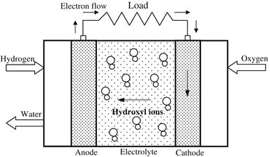
FIGURE 7.10 Schematic diagram of an alkaline fuel cell (AFC).
AFCs are the cheapest fuel cells to manufacture. This is because the catalyst required on the electrodes can be selected from a number of materials that are relatively inexpensive compared with the catalysts required for other types of fuel cells (U.S. Department of Energy, 2000).
The charge carrier for an AFC is the hydroxyl ion (OH−) transferred from the cathode to the anode, where it reacts with hydrogen to produce water and electrons. Water formed at the anode is transferred back to the cathode to regenerate hydroxyl ions. When operated, the AFC produces electricity and the by-product is heat.
Phosphoric acid fuel cell (PAFC)
Phosphoric acid fuel cells (PAFCs) were the first fuel cells to be commercialized. They were developed in the mid-1960s, have been field tested since the 1970s, and they have improved significantly in stability, performance, and cost. A schematic diagram of a PAFC is shown in Figure 7.11. The efficiency of a PAFC in generating electricity is greater than 40%. Simple construction, low electrolyte volatility, and long-term stability are additional advantages. Phosphoric acid (H3PO4) concentrated to 100% is used for the electrolyte in this fuel cell, which operates at 150–220 °C, since the ionic conductivity of phosphoric acid is low at low temperatures. The relative stability of concentrated phosphoric acid is high compared with other common acids. In addition, the use of concentrated acid minimizes the water vapor pressure, so water management in the cell is not difficult. The matrix universally used to retain the acid is silicon carbide and the electrocatalyst in both the anode and the cathode is platinum (Pt).
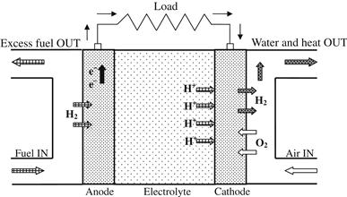
FIGURE 7.11 Schematic diagram of phosphoric acid fuel cell (PAFC).
The charge carrier in this type of fuel cell is the hydrogen ion (H+, proton). The hydrogen introduced at the anode is split into its protons and electrons. The protons are transferred through the electrolyte and combine with the oxygen, usually from air, at the cathode to form water. In addition, CO2 does not affect the electrolyte or cell performance and PAFCs can therefore be easily operated with reformed fossil fuels.
Approximately 75 MW of PAFC generating capacity has been installed and is operating. Typical installations include hotels, hospitals, and electric utilities in Japan, Europe, and the United States (FCTec, 2008).
Molten carbonate fuel cell (MCFC)
Molten carbonate fuel cells (MCFCs) belong to the class of high-temperature fuel cells. The higher operating temperature allows them to use natural gas directly without the need for a fuel processor. A schematic diagram illustrating the working principle of an MCFC is shown in Figure 7.12. MCFCs work quite differently from other fuel cells. The electrolyte in this fuel cell is composed of a molten mixture of carbonate salts. The fuel cell operates at 600–700 °C, at which the alkali carbonates form a highly conductive molten salt, with carbonate ions providing ionic conduction. Two mixtures are currently used: the lithium carbonate and potassium carbonate or the lithium carbonate and sodium carbonate. These ions flow from the cathode to the anode, where they combine with hydrogen to yield water, carbon dioxide, and electrons. These electrons are routed through an external circuit back to the cathode, generating electricity and the by-product, heat. At the high operating temperatures in MCFCs, nickel (anode) and nickel oxide (cathode) are adequate to promote reaction, that is, noble metals are not required.
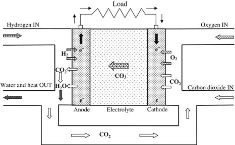
FIGURE 7.12 Schematic diagram of molten carbonate fuel cell (MCFC).
Compared with the lower temperature PAFCs and PEMFCs, the higher operating temperature of MCFCs has both advantages and disadvantages (FCTec, 2008). The advantages include:
1. At the higher operating temperature, fuel reforming of natural gas can occur internally, eliminating the need for an external fuel processor.
2. The ability to use standard materials for construction, such as stainless steel sheet, and allow the use of nickel-based catalysts on the electrodes.
3. The by-product heat from an MCFC can be used to generate high-pressure steam that can be used in many industrial and commercial applications.
The disadvantages are mainly due to the high temperatures and include:
1. High temperature requires significant time to reach operating conditions and responds slowly to changing power demands. These characteristics make MCFCs more suitable for constant power applications.
2. The carbonate electrolyte can cause electrode corrosion problems.
3. As CO2 is consumed at the anode and transferred to the cathode, its introduction into the air stream and its control are problematic for achieving optimum performance.
Solid oxide fuel cell (SOFC)
Solid oxide fuel cells (SOFCs) can be operated over a wide temperature range, from 600 to 1000 °C. They have been in development since the late 1950s and are the highest temperature fuel cells developed to allow a number of fuels to be used. A diagram of an SOFC is shown in Figure 7.13. To operate at such high temperatures, the electrolyte is a thin, solid ceramic material (solid oxide) conductive to oxygen ions (O2−), which is the charge carrier. At the cathode, the oxygen molecules from the air are split into oxygen ions with the addition of four electrons. The oxygen ions are conducted through the electrolyte and combine with hydrogen at the anode, releasing four electrons. The electrons travel an external circuit providing electric power and producing heat as a by-product. The operating efficiency in generating electricity is among the highest of the fuel cells, at about 60% (FCTec, 2008).
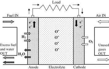
FIGURE 7.13 Schematic diagram of solid oxide fuel cell (SOFC).
The solid electrolyte is impermeable to gas crossover from one electrode to another, in contrast to liquid electrolytes, where the electrolyte is contained in some porous supporting structure.
SOFCs operate at extremely high temperatures, so a significant amount of time is required to reach operating temperature. They also respond slowly to changes in electricity demand; thus, they are suitable for high-power applications, including industrial and large-scale central electricity generating stations.
The advantages of the high operating temperature of SOFCs are that it enables them to tolerate relatively impure fuels, such as those obtained from the gasification of coal or gases from industrial processes, and allows cogeneration applications, such as to create high-pressure steam that can be used in many applications. Furthermore, combining a high-temperature fuel cell with a turbine into a hybrid fuel cell further increases the overall efficiency of generating electricity, with a potential of an efficiency of more than 70% (FCTec, 2008). The disadvantage of SOFCs is that the high temperatures require more expensive construction materials.
Proton exchange membrane fuel cell (PEMFC)
Proton exchange membrane fuel cells (PEMFCs), also known as polymer electrolyte membrane fuel cells, are believed to be the best type of fuel cell for automobile applications that could eventually replace the gasoline and diesel internal combustion engines. First used in the 1960s for the NASA Gemini Program, PEMFCs are currently being developed and demonstrated for systems ranging from 1 W to 2 kW (FCTec, 2008). For a schematic diagram of this type of fuel cell please refer to the diagram for the PAFC, as it is very similar.
PEMFCs use a solid polymer membrane in the form of a thin plastic film as the electrolyte. This polymer is permeable to protons when it is saturated with water, but it does not conduct electrons. The fuel for the PEMFC is hydrogen and the charge carrier is the hydrogen ion (proton). At the anode, the hydrogen molecule is split into hydrogen ions (protons) and electrons. The hydrogen ions move across the electrolyte to the cathode while the electrons flow through an external circuit and produce electric power. Oxygen, usually in the form of air, is supplied to the cathode and combines with the electrons and the hydrogen ions to produce water (FCTec, 2008).
The electrolyte in these fuel cells is an ion exchange membrane (fluorinated sulfonic acid polymer or other similar polymer) that is an excellent proton conductor. The only liquid used in this fuel cell is water; thus, corrosion problems are minimal. Water management in the membrane is critical for efficient performance, as the fuel cell must operate under conditions where the by-product water does not evaporate faster than it is produced, because the membrane must be kept hydrated. Because of the limitation on the operating temperature imposed by the polymer, which is usually less than 120 °C, and problems with water balance, an H2-rich gas with minimal or no CO, which is a contaminant at low temperature, is used. Higher catalyst loading (Pt in most cases) is required for both the anode and the cathode (U.S. Department of Energy, 2000).
The advantages of PEMFCs are that they generate more power than other types of fuel cells, for a given volume or weight of fuel cell. This characteristic makes them compact and lightweight. Because the operating temperature is less than 100 °C, rapid start up is achieved.
Since the electrolyte is a solid material, the sealing of the anode and cathode gases is simpler with a solid electrolyte, compared with a liquid; therefore, a lower cost is required to manufacture the cell. The solid electrolyte is also less sensitive to orientation and the corrosion problems are lower, compared with many of the other electrolytes, which leads to a longer cell and stack life.
One major disadvantage of the PEMFC is that the electrolyte must be saturated with water to operate optimally; therefore, careful control of the moisture of the anode and cathode streams is required. The high cost of platinum is another disadvantage.
Other types of fuels cells, not described in this book, include the direct methanol fuel cell (DMFC), regenerative fuel cell (RFC), zinc-air fuel cell (ZAFC), intermediate temperature solid oxide fuel cell (ITSOFC), and tubular solid oxide fuel cell (TSOFC). Interested readers can find information on these cells in other publications dedicated to the subject.
7.3.3 Materials processing
Solar energy material processing involves affecting the chemical conversion of materials by their direct exposure to concentrated solar energy. For this purpose, solar furnaces are used made of high-concentration, hence, high-temperature, collectors of the parabolic dish or heliostat type. Solar energy can also assist in the processing of energy-intensive high-temperature materials, as in the production of solar aluminum, the manufacture of which is one of the most energy-intensive processes. It also includes applications related to the production of high-added-value products, from fullerenes, which are large carbon molecules with major potential in commercial applications in semi- and superconductors, to commodity products such as cement (Norton, 2001). None of these processes, however, has achieved large-scale commercial adoption. Some pilot systems are described briefly here.
A solar thermochemical process developed by Steinfeld et al. (1996) combines the reduction of zinc oxide with reforming of natural gas, leading to the co-production of zinc, hydrogen, and carbon monoxide. At equilibrium, chemical composition in a blackbody solar reactor operated at a temperature of about 1000 °C, atmospheric pressure and solar concentration of 2000, efficiencies between 0.4 and 0.65 have been obtained, depending on product heat recovery. A 5 kW solar chemical reactor was employed to demonstrate this technology in a high-flux solar furnace. Particles of zinc oxide were introduced continuously in a vortex flow, and natural gas contained within a solar cavity receiver was exposed to concentrated insolation from a heliostat field. The zinc oxide particles are exposed directly to the high radiative flux, avoiding the efficiency penalty and cost of heat exchangers.
A 2 kW concentrating solar furnace was used to study the thermal decomposition of titanium dioxide at temperatures of 2000–2500 °C in an argon atmosphere (Palumbo et al., 1995). The decomposition rate was limited by the rate at which oxygen diffuses from the liquid–gas interface. It was shown that this rate is accurately predicted by a numerical model, which couples the equations of chemical equilibrium and steady-state mass transfer (Palumbo et al., 1995).
7.3.4 Solar detoxification
Another field of solar chemistry applications is solar photochemistry. Solar photochemical processes make use of the spectral characteristics of the incoming solar radiation to effect selective catalytic transformations, which find application in the detoxification of air and water and the processing of fine chemical commodities.
Solar detoxification achieves photocatalytic treatment of non-biodegradable persistent chlorinated water contaminants typically found in chemical production processes. For this purpose, parabolic trough collectors with glass absorbers are usually employed and the high intensity of solar radiation is used for the photocatalytic decomposition of organic contaminants. A development in photocatalytic detoxification and disinfection of water and air is presented by Goswami (1999). This process uses ultraviolet energy, available in sunlight, in conjunction with a photocatalyst (titanium dioxide), to decompose organic chemicals into non-toxic compounds (Mehos et al., 1992). Another application concerns the development of a prototype employing lower concentration compound parabolic collectors (Grasse, 1998).
The use of a compound parabolic concentrator technology for commercial solar detoxification applications is presented by Blanco et al. (1999). The objective is to develop a simple, efficient, and commercially competitive water treatment technology. A demonstration facility was erected at Plataforma Solar de Almeria in southern Spain.
Leave a Reply