The quest for a safe and comfortable environment has always been one of the main preoccupations of the human race. In ancient times, people used the experience gained over many years to utilize in the best possible way the available resources to achieve adequate living conditions. Central heating was pioneered by the Romans, using double floors and passing the fumes of a fire through the floor cavity. Also in Roman times, windows were covered for the first time with materials such as mica or glass. Thus, light was admitted in the house without letting in wind and rain (Kreider and Rabl, 1994). The Iraqis, on the other hand, utilized the prevailing wind to take advantage of the cool night air and provide a cooler environment during the day (Winwood et al., 1997). Additionally, running water was employed to provide some evaporative cooling.
As late as the 1960s, though, house comfort conditions were only for the few. From then onward, central air-conditioning systems became common in many countries, due to the development of mechanical refrigeration and the rise in the standard of living. The oil crisis of the 1970s stimulated intensive research aimed at reducing energy costs. Also, global warming and ozone depletion and the escalating costs of fossil fuels over the last few years have forced governments and engineering bodies to re-examine the whole approach to building design and control. Energy conservation in the sense of fuel saving is also of great importance.
During recent years, research aimed at the development of technologies that can offer reductions in energy consumption, peak electrical demand, and energy costs without lowering the desired level of comfort conditions has intensified. Alternative cooling technologies that can be applied to residential and commercial buildings, under a wide range of weather conditions, are being developed. These include night cooling with ventilation, evaporative cooling, desiccant cooling, and slab cooling. The design of buildings employing low-energy cooling technologies, however, presents difficulties and requires advanced modeling and control techniques to ensure efficient operation.
Another method that can be used to reduce energy consumption is ground cooling. This is based on the heat loss dissipation from a building to the ground, which during the summer has a lower temperature than the ambient. This dissipation can be achieved either by direct contact of an important part of the building envelope with the ground or by blowing into the building air that has first been passed through an earth-to-air heat exchanger (Argiriou, 1997).
The role of designers and architects is very important, especially with respect to solar energy control, the utilization of thermal mass, and the natural ventilation of buildings, as was seen in Section 6.2.6. In effective solar energy control, summer heat gains must be reduced, while winter solar heat gains must be maximized. This can be achieved by proper orientation and shape of the building, the use of shading devices, and the selection of proper construction materials. Thermal mass, especially in hot climates with diurnal variation of ambient temperatures exceeding 10 °C, can be used to reduce the instantaneous high cooling loads, reduce energy consumption, and attenuate indoor temperature swings. Correct ventilation can enhance the roles of both solar energy control and thermal mass.
Reconsideration of the building structure; the readjustment of capital cost allocations, i.e., investing in energy conservation measures that may have a significant influence on thermal loads; and improvements in equipment and maintenance can minimize the energy expenditure and improve thermal comfort.
In intermediate seasons in hot, dry climates, processes such as evaporative cooling can offer energy conservation opportunities. However, in summertime, due to the high temperatures, low-energy cooling technologies alone cannot satisfy the total cooling demand of domestic dwellings. For this reason active cooling systems are required. Vapor compression cooling systems are usually used, powered by electricity, which is expensive and its production depends mainly on fossil fuel. In such climates, one source abundantly available is solar energy, which could be used to power an active solar cooling system based on the absorption cycle. The problem with solar absorption machines is that they are more expensive compared to vapor compression machines, and until recently, they were not readily available in the small-capacity range applicable to domestic cooling applications. Reducing the use of conventional vapor compression air-conditioning systems will also reduce their effect on both global warming and ozone layer depletion.
The integration of the building envelope with an absorption system should offer better control of the internal environment. Two basic types of absorption units are available: ammonia–water and lithium bromide (LiBr) water units. The latter are more suitable for solar applications since their operating (generator) temperature is lower and thus more readily obtainable with low-cost solar collectors (Florides et al., 2001).
The solar cooling of buildings is an attractive idea because the cooling loads and availability of solar radiation are in phase. Additionally, the combination of solar cooling and heating greatly improves the use factors of collectors compared to heating alone. Solar air conditioning can be accomplished by three types of systems: absorption cycles, adsorption (desiccant) cycles, and solar mechanical processes. Some of these cycles are also used in solar refrigeration systems and are described in the following sections.
Solar cooling can be considered for two related processes: to provide refrigeration for food and medicine preservation and to provide comfort cooling. Solar refrigeration systems usually operate at intermittent cycles and produce much lower temperatures (ice) than in air conditioning. When the same systems are used for space cooling they operate on continuous cycles. The cycles employed for solar refrigeration are absorption and adsorption. During the cooling portion of the cycles, the refrigerant is evaporated and re-absorbed. In these systems, the absorber and generator are separate vessels. The generator can be an integral part of the collector, with refrigerant absorbent solution in the tubes of the collector circulated by a combination of a thermosiphon and a vapor lift pump.
Many options enable the integration of solar energy into the process of “cold” production. Solar refrigeration can be accomplished by using either a thermal energy source supplied from a solar collector or electricity supplied from photovoltaics. This can be achieved by using either thermal adsorption or absorption units, or conventional vapor compression refrigeration equipment powered by photovoltaics. Solar refrigeration is employed mainly to cool vaccine stores in areas with no public electricity.
Photovoltaic refrigeration, although it uses standard refrigeration equipment, which is an advantage, has not achieved widespread use because of the low efficiency and high cost of the photovoltaic cells. As the photovoltaics-operated vapor compression systems do not differ in operation from the public utility systems, these are not covered in this book and details are given only on the solar adsorption and absorption units, with more emphasis on the latter.
Solar cooling is more attractive for the southern countries of the Northern Hemisphere and the northern countries of the Southern Hemisphere. Solar cooling systems are particularly applicable to large applications (e.g. commercial buildings) that have high cooling loads for large periods of the year. Such systems in combination with solar heating can make more efficient use of solar collectors, which would be idle during the cooling season. Generally, however, there is much less experience with solar cooling than solar heating systems.
Solar cooling systems can be classified into three categories: solar-sorption cooling, solar-mechanical systems, and solar-related systems examined briefly in the following sections (Florides et al., 2002a).
Solar-sorption cooling
Sorbents are materials that have an ability to attract and hold other gases or liquids. Desiccants are sorbents that have a particular affinity for water. The process of attracting and holding moisture is described as either absorption or adsorption, depending on whether the desiccant undergoes a chemical change as it takes on moisture. Absorption changes the desiccant the way, for example, table salt changes from a solid to a liquid as it absorbs moisture. Adsorption, on the other hand, does not change the desiccant except by the addition of the weight of water vapor, similar in some ways to a sponge soaking up the water (ASHRAE, 2005).
Compared to an ordinary cooling cycle, the basic idea of an absorption system is to avoid compression work. This is done by using a suitable working pair: a refrigerant and a solution that can absorb the refrigerant.
Absorption systems are similar to vapor-compression air-conditioning systems but differ in the pressurization stage. In general, an evaporating refrigerant is absorbed by an absorbent on the low-pressure side. Combinations include lithium bromide–water (LiBr–H2O), where water vapor is the refrigerant, and ammonia–water (NH3–H2O) systems, where ammonia is the refrigerant (Keith et al., 1996).
Adsorption cooling is the other group of sorption air conditioners that utilizes an agent (the adsorbent) to adsorb the moisture from the air (or dry any other gas or liquid), then uses the evaporative cooling effect to produce cooling. Solar energy can be used to regenerate the drying agent. Solid adsorbents include silica gels, zeolites, synthetic zeolites, activated alumina, carbons, and synthetic polymers (ASHRAE, 2005). Liquid adsorbents can be triethylene glycol solutions of lithium chloride and LiBr solutions.
More details of these systems are given in separate sections further on.
Solar-mechanical systems
Solar-mechanical systems utilize a solar-powered prime mover to drive a conventional air-conditioning system. This can be done by converting solar energy into electricity by means of photovoltaic devices, then utilizing an electric motor to drive a vapor compressor. The photovoltaic panels, however, have a low field efficiency of about 10–15%, depending on the type of cells used, which results in low overall efficiencies for the system.
The solar-powered prime mover can also be a Rankine engine. In a typical system, energy from the collector is stored, then transferred to a heat exchanger, and finally energy is used to drive the heat engine (see Chapter 10). The heat engine drives a vapor compressor, which produces a cooling effect at the evaporator. As shown in Figure 6.18, the efficiency of the solar collector decreases as the operating temperature increases, whereas the efficiency of the heat engine of the system increases as the operating temperature increases. The two efficiencies meet at a point (A in Figure 6.18), providing an optimum operating temperature for a steady-state operation. The combined system has overall efficiencies between 17 and 23%.
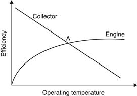
FIGURE 6.18 Collector and power cycle efficiencies as a function of operating temperature.
Due to the diurnal cycle, both the cooling load and the storage tank temperature vary through the day. Therefore, designing such a system presents appreciable difficulties. When a Rankine heat engine is coupled with a constant-speed air conditioner, the output of the engine seldom matches the input required by the air conditioner. Therefore, auxiliary energy must be supplied when the engine output is less than that required; otherwise, excess energy may be used to produce electricity for other purposes.
Solar-related air conditioning
Some components of systems installed for the purpose of heating a building can also be used to cool it but without the direct use of solar energy. Examples of these systems can be heat pumps, rock bed regenerators, and alternative cooling technologies or passive systems. Heat pumps were examined in Section 6.3.5. The other two methods are briefly introduced here.
• Rock bed regenerator. Rock bed (or pebble bed) storage units of solar air-heating systems can be night-cooled during summer to store “cold” for use the following day. This can be accomplished during the night when the temperatures and humidities are low by passing outside air through an optional evaporative cooler, through the pebble bed, and to the exhaust. During the day, the building can be cooled by passing the room air through the pebble bed. A number of applications using pebble beds for a solar energy storage are given by Hastings (1999). For such systems, airflow rates should be kept to a minimum so as to minimize fan power requirements without affecting the performance of the pebble bed. Therefore, an optimization process should be followed as part of the design.
• Alternative cooling technologies or passive systems. Passive cooling is based on the transfer of heat by natural means from a building to environmental sinks, such as clear skies, the atmosphere, the ground, and water. The transfer of heat can be by radiation, naturally occurring wind, airflow due to temperature differences, conduction to the ground, or conduction and convection to bodies of water. It is usually up to the designer to select the most appropriate type of technology for each application. The options depend on the climate type.
More details for the adsorption and absorption systems follow.
6.4.1 Adsorption units
Porous solids, called adsorbents, can physically and reversibly adsorb large volumes of vapor, called the adsorbate. Though this phenomenon, called solar adsorption, was recognized in nineteenth century, its practical application in the field of refrigeration is relatively recent. The concentration of adsorbate vapors in a solid adsorbent is a function of the temperature of the pair, i.e., the mixture of adsorbent and adsorbate and the vapor pressure of the latter. The dependence of adsorbate concentration on temperature, under constant pressure conditions, makes it possible to adsorb or desorb the adsorbate by varying the temperature of the mixture. This forms the basis of the application of this phenomenon in the solar-powered intermittent vapor sorption refrigeration cycle.
An adsorbent–refrigerant working pair for a solar refrigerator requires the following characteristics:
1. A refrigerant with a large latent heat of evaporation.
2. A working pair with high thermodynamic efficiency.
3. A low heat of desorption under the envisaged operating pressure and temperature conditions.
Water–ammonia has been the most widely used sorption refrigeration pair, and research has been undertaken to utilize the pair for solar-operated refrigerators. The efficiency of such systems is limited by the condensing temperature, which cannot be lowered without introduction of advanced and expensive technology. For example, cooling towers or desiccant beds have to be used to produce cold water to condensate ammonia at lower pressure. Among the other disadvantages inherent in using water and ammonia as the working pair are the heavy-gauge pipe and vessel walls required to withstand the high pressure, the corrosiveness of ammonia, and the problem of rectification, i.e., removing water vapor from ammonia during generation. A number of solid adsorption working pairs, such as zeolite–water, zeolite–methanol, and activated carbon–methanol, have been studied to find the one that performed best. The activated carbon–methanol working pair was found to perform the best (Norton, 1992).
Many cycles have been proposed for adsorption cooling and refrigeration (Dieng and Wang, 2001). The principle of operation of a typical system is indicated in Figure 6.19. The process followed at the points from 1 to 9 of Figure 6.19 is traced on the psychrometric chart depicted in Figure 6.20. Ambient air is heated and dried by a dehumidifier from point 1 to 2, regeneratively cooled by exhaust air in 2 to 3, evaporatively cooled in 3 to 4, and introduced into the building. Exhaust air from the building is evaporatively cooled from points 5 to 6, heated to 7 by the energy removed from the supply air in the regenerator, heated by solar energy or another source to 8, then passed through the dehumidifier, where it regenerates the desiccant.
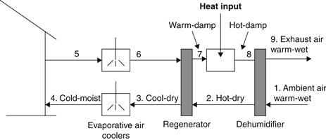
FIGURE 6.19 Schematic of a solar adsorption system.
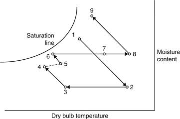
FIGURE 6.20 Psychrometric diagram of a solar adsorption process.
The selection of the adsorbing agent depends on the size of the moisture load and application.
Rotary solid desiccant systems are the most common for continuous removal of moisture from the air. The desiccant wheel rotates through two separate air streams. In the first stream, the process air is dehumidified by adsorption, which does not change the physical characteristics of the desiccant; in the second stream the reactivation or regeneration air, which is first heated, dries the desiccant. Figure 6.21 is a schematic of a possible solar-powered adsorption system.
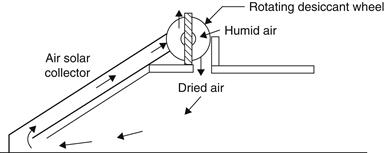
FIGURE 6.21 Solar adsorption cooling system.
When the drying agent is a liquid, such as triethylene glycol, the agent is sprayed into an absorber, where it picks up moisture from the building air. Then, it is pumped through a sensible heat exchanger to a separation column, where it is sprayed into a stream of solar-heated air. The high-temperature air removes water from the glycol, which then returns to the heat exchanger and the absorber. Heat exchangers are provided to recover sensible heat, maximize the temperature in the separator, and minimize the temperature in the absorber. This type of cycle is marketed commercially and used in hospitals and large installations (Duffie and Beckman, 1991).
The energy performance of these systems depends on the system configuration, geometries of dehumidifiers, properties of adsorbent agent, and the like, but generally the COP of this technology is around 1.0. It should be noted, however, that in hot, dry climates the desiccant part of the system may not be required.
Because complete physical property data are available for only a few potential working pairs, the optimum performance remains unknown at the moment. In addition, the operating conditions of a solar-powered refrigerator, i.e., generator and condenser temperature, vary with its geographical location (Norton, 1992).
The development of three solar-biomass adsorption air-conditioning and refrigeration systems is presented by Critoph (2002). All systems use active carbon–ammonia adsorption cycles and the principle of operation and performance prediction of the systems are given.
Thorpe (2002) presented an adsorption heat pump system that uses ammonia with a granular active adsorbate. A high COP is achieved and the cycle is suitable for the use of heat from high-temperature (150–200 °C) solar collectors for air conditioning.
6.4.2 Absorption units
Absorption is the process of attracting and holding moisture by substances called desiccants. Desiccants are sorbents, i.e., materials that have an ability to attract and hold other gases or liquids that have a particular affinity for water. During absorption, the desiccant undergoes a chemical change as it takes on moisture; an example mentioned before is table salt, which changes from a solid to a liquid as it absorbs moisture. The characteristic of the binding of desiccants to moisture makes the desiccants very useful in chemical separation processes (ASHRAE, 2005).
Absorption machines are thermally activated, and they do not require high input shaft power. Therefore, where power is unavailable or expensive, or where there is waste, geothermal, or solar heat available, absorption machines could provide reliable and quiet cooling. Absorption systems are similar to vapor compression air-conditioning systems but differ in the pressurization stage. In general, an absorbent, on the low-pressure side, absorbs an evaporating refrigerant. The most usual combinations of fluids include LiBr–H2O, where water vapor is the refrigerant, and ammonia–water (NH3–H2O) systems, where ammonia is the refrigerant.
Absorption refrigeration systems are based on extensive development and experience in the early years of the refrigeration industry, in particular for ice production. From the beginning, its development has been linked to periods of high energy prices. Recently, however, there has been a great resurgence of interest in this technology not only because of the rise in the energy prices but mainly due to the social and scientific awareness about the environmental degradation, which is related to the energy generation.
The pressurization is achieved by dissolving the refrigerant in the absorbent, in the absorber section (Figure 6.22). Subsequently, the solution is pumped to a high pressure with an ordinary liquid pump. The addition of heat in the generator is used to separate the low-boiling refrigerant from the solution. In this way, the refrigerant vapor is compressed without the need for large amounts of mechanical energy that the vapor compression air-conditioning systems demand.
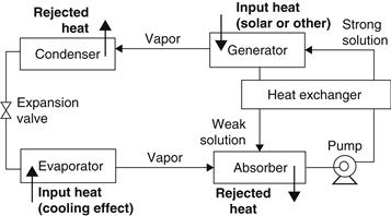
FIGURE 6.22 Basic principle of the absorption air-conditioning system.
The remainder of the system consists of a condenser, expansion valve, and evaporator, which function in a similar way as in a vapor compression air-conditioning system.
Lithium bromide–water absorption systems
The LiBr–H2O system operates at a generator temperature in the range of 70–95 °C, with water used as a coolant in the absorber and condenser, and has a COP higher than the NH3–H2O systems. The COP of this system is between 0.6 and 0.8. A disadvantage of the LiBr–H2O systems is that their evaporator cannot operate at temperatures much below 5 °C, since the refrigerant is water vapor. Commercially available absorption chillers for air-conditioning applications usually operate with a solution of lithium bromide in water and use steam or hot water as the heat source. Two types of chillers are available on the market: the single effect and the double effect.
The single-effect absorption chiller is used mainly for building cooling loads, where chilled water is required at 6–7 °C. The COP will vary to a small extent with the heat source and the cooling water temperatures. Single effect chillers can operate with hot water temperature ranging from about 70 to 150 °C when water is pressurized (Florides et al., 2003).
The double-effect absorption chiller has two stages of generation to separate the refrigerant from the absorbent. Therefore, the temperature of the heat source needed to drive the high-stage generator is essentially higher than that needed for the single-effect machine and is in the range of 155–205 °C. Double-effect chillers have a higher COP of about 0.9–1.2 (Dorgan et al., 1995). Although double-effect chillers are more efficient than the single-effect machines, they are obviously more expensive to purchase. However, every individual application must be considered on its own merits, since the resulting savings in capital cost of the single-effect units can largely offset the extra capital cost of the double-effect chiller.
The Carrier Corporation pioneered lithium-bromide absorption chiller technology in the United States, with the early single-effect machines introduced around 1945. Due to the success of the product, soon other companies joined in production. The absorption business thrived until 1975. Then, the generally held belief that natural gas supplies were lessening led to U.S. government regulations prohibiting the use of gas in new constructions and, together with the low cost of electricity, led to the declination of the absorption refrigeration market (Keith, 1995). Today the major factor in the decision on the type of system to install for a particular application is the economic trade-off between different cooling technologies. Absorption chillers typically cost less to operate, but they cost more to purchase than vapor compression units. The payback period depends strongly on the relative cost of fuel and electricity, assuming that the operating cost for the needed heat is less than the operating cost for electricity.
The technology was exported to Japan from the United States early in the 1960s, and Japanese manufacturers set a research and development program to further improve the absorption systems. The program led to the introduction of the direct-fired double-effect machines with improved thermal performance.
Today gas-fired absorption chillers deliver 50% of the commercial space-cooling load worldwide but less than 5% in the United States, where electricity-driven vapor compression machines carry the majority of the load (Keith, 1995).
Many researchers have developed solar-assisted absorption refrigeration systems. Most of them have been produced as experimental units, and computer codes were written to simulate the systems. Some of these designs are presented here.
Hammad and Audi (1992) described the performance of a non-storage, continuous, solar-operated absorption refrigeration cycle. The maximum ideal coefficient of performance of the system was determined to be equal to 1.6, while the peak actual coefficient of performance was determined to be equal to 0.55.
Haim et al. (1992) performed a simulation and analysis of two open-cycle absorption systems. Both systems comprise a closed absorber and evaporator, as in conventional single-stage chillers. The open part of the cycle is the regenerator, used to re-concentrate the absorber solution by means of solar energy. The analysis was performed with a computer code developed for modular simulation of absorption systems under varying cycle configurations (open and closed cycle systems) and with different working fluids. Based on the specified design features, the code calculates the operating parameters in each system. Results indicate that there is a definite performance advantage of the direct regeneration system over the indirect one.
Hawlader et al. (1993) developed a LiBr absorption cooling system employing an 11 × 11 m collector–regenerator unit. They also developed a computer model, which they validated against real experimental values with good agreement. The experimental results showed a regeneration efficiency varying between 38% and 67% and the corresponding cooling capacities ranged from 31 to 72 kW.
Ghaddar et al. (1997) presented the modeling and simulation of a solar absorption system for Beirut. The results showed that each ton of refrigeration requires a minimum collector area of 23.3 m2 with an optimum water-storage capacity ranging from 1000 to 1500 l for the system to operate solely on the solar energy for about 7 h/day. The monthly solar fraction of total energy use in cooling is determined as a function of the solar collector area and storage tank capacity. The economic analysis performed showed that the solar cooling system is marginally competitive only when it is combined with domestic water heating.
Erhard and Hahne (1997) simulated and tested a solar-powered absorption cooling machine. The main part of the device is an absorber–desorber unit, which is mounted inside a concentrating solar collector. Results obtained from field tests are discussed and compared with the results obtained from a simulation program developed for this purpose.
Hammad and Zurigat (1998) described the performance of a 1.5 ton solar cooling unit. The unit comprises a 14 m2 flat-plate solar collector system and five shell and tube heat exchangers. The unit was tested in April and May in Jordan. The maximum value obtained for actual coefficient of performance was 0.85.
Zinian and Ning (1999) described a solar absorption air-conditioning system that uses an array of 2160 evacuated tubular collectors of total aperture area of 540 m2 and a LiBr absorption chiller. Thermal efficiencies of the collector array are 40% for space cooling, 35% for space heating, and 50% for domestic water heating. It was found that the cooling efficiency of the entire system is around 20%.
Ameel et al. (1995) gave performance predictions of alternative low-cost absorbents for open-cycle absorption using a number of absorbents. The most promising of the absorbents considered was a mixture of two elements, lithium chloride and zinc chloride. The estimated capacities per unit absorber area were 50–70% less than those of LiBr systems.
Recently, Calise (2012) presented a dynamic model of an innovative solar heating and cooling system (SHC) based on the coupling of parabolic trough collectors with a double-stage LiBr–H2O absorption chiller, in which the auxiliary energy for both heating and cooling is supplied by a biomass-fired heater. The consumption of non-renewable energy resources is only due to the small amount of electrical energy consumed by some auxiliary devices. A case study is presented, in which the SHC provides space heating and cooling and domestic hot water for a small university hall, for the whole year. Both the SHC system and the building were dynamically simulated in TRNSYS. The analysis was also performed for a similar SHC in which the biomass heater was replaced by a gas-fired heater, in order to evaluate the influence of biomass on the overall system’s economic and energetic performance.
A new family of ICPC designs developed by Winston et al. (1999) allows a simple manufacturing approach to be used and solves many of the operational problems of previous ICPC designs (see Section 3.1.3). A low concentration ratio that requires no tracking is used with an off-the-shelf, 20 ton, double-effect, LiBr, direct-fired absorption chiller, modified to work with hot water. The new ICPC design and double-effect chiller were able to produce cooling energy for the building using a collector field that was about half the size of that required for a more conventional collector and chiller.
A method to design, construct, and evaluate the performance of a single-stage LiBr–H2O absorption machine is presented by Florides et al. (2003). In this work, the necessary heat and mass transfer relations and appropriate equations describing the properties of the working fluids are specified. Information on designing the heat exchangers of the LiBr–H2O absorption unit is also presented. Single-pass, vertical tube heat exchangers have been used for the absorber and the evaporator. The solution heat exchanger was designed as a single-pass annulus heat exchanger. The condenser and the generator were designed using horizontal tube heat exchangers. Another valuable source of LiBr–H2O system properties is the program EES (Engineering Equation Solver), which can also be used to solve the equations required to design such a system (Klein, 1992).
If power generation efficiency is considered, the thermodynamic efficiency of absorption cooling is very similar to that of the electrically driven compression refrigeration system. The benefits of the solar systems, however, are very obvious when environmental pollution is considered. This is accounted for by the total equivalent warming impact (TEWI) of the system. As proven by Florides et al. (2002c) in a study of domestic size systems, the TEWI of the absorption system was 1.2 times smaller than that of the conventional system.
Thermodynamic analysis
Compared to an ordinary cooling cycle, the basic idea of an absorption system is to avoid compression work by using a suitable working pair. The working pair consists of a refrigerant and a solution that can absorb the refrigerant. A more detailed schematic of the LiBr–H2O absorption system is shown in Figure 6.23 (Kizilkan et al., 2007), and a schematic presentation on a pressure–temperature diagram is illustrated in Figure 6.24.
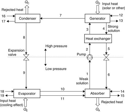
FIGURE 6.23 Schematic diagram of an absorption refrigeration system.
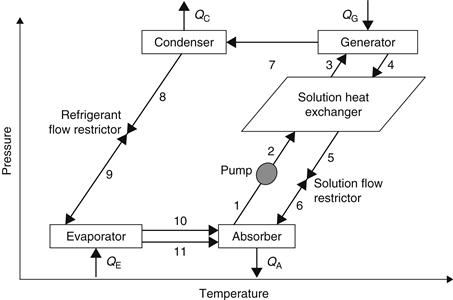
FIGURE 6.24 Pressure–temperature diagram of a single effect, LiBr–water absorption cycle.
The main components of an absorption refrigeration system are the generator, absorber, condenser, and evaporator. In the model shown, QG is the heat input rate from the heat source to the generator, QC and QA are the heat rejection rates from condenser and absorber to the heat sinks, respectively, and QE is the heat input rate from the cooling load to the evaporator.
With reference to the numbering system shown in Figure 6.23, at point 1, the solution is rich in refrigerant and a pump (1–2) forces the liquid through a heat exchanger to the generator. The temperature of the solution in the heat exchanger is increased (2–3).
In the generator, thermal energy is added and refrigerant boils off the solution. The refrigerant vapor (7) flows to the condenser, where heat is rejected as the refrigerant condenses. The condensed liquid (8) flows through a flow restrictor to the evaporator (9). In the evaporator, the heat from the load evaporates the refrigerant, which flows back to the absorber (10). A small portion of the refrigerant leaves the evaporator as a liquid spillover (11). At the generator exit (4), the stream consists of absorbent–refrigerant solution, which is cooled in the heat exchanger. From points 6 to 1, the solution absorbs refrigerant vapor from the evaporator and rejects heat through a heat exchanger. This procedure can also be presented in a Duhring chart (Figure 6.25). This chart is a pressure–temperature graph, where diagonal lines represent constant LiBr mass fraction, with the pure water line at the left.
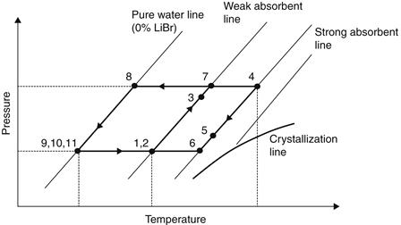
FIGURE 6.25 Duhring chart of the water–lithium bromide absorption cycle.
For the thermodynamic analysis of the absorption system, the principles of mass conservation and the first and second laws of thermodynamics are applied to each component of the system. Each component can be treated as a control volume with inlet and outlet streams, heat transfer, and work interactions. In the system, mass conservation includes the mass balance of each material of the solution. The governing equations of mass and type of material conservation for a steady-state, steady-flow system are (Herold et al., 1996):
![]() (6.68)
(6.68)
![]() (6.69)
(6.69)
where ![]() is the mass flow rate and x is mass concentration of LiBr in the solution. The first law of thermodynamics yields the energy balance of each component of the absorption system as follows:
is the mass flow rate and x is mass concentration of LiBr in the solution. The first law of thermodynamics yields the energy balance of each component of the absorption system as follows:
![]() (6.70)
(6.70)
An overall energy balance of the system requires that the sum of the generator, evaporator, condenser, and absorber heat transfer must be 0. If the absorption system model assumes that the system is in a steady state and that the pump work and environmental heat losses are neglected, the energy balance can be written as:
![]() (6.71)
(6.71)
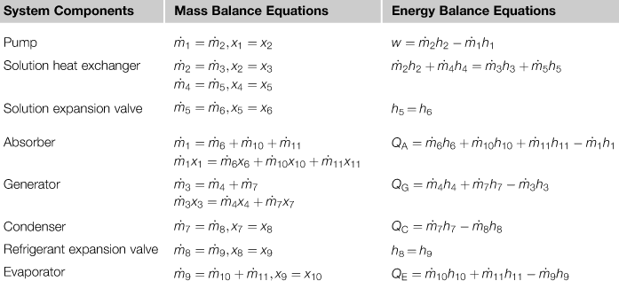
The energy, mass concentrations, and mass balance equations of the various components of an absorption system are given in Table 6.2 (Kizilkan et al., 2007). The equations of Table 6.2 can be used to estimate the energy, mass concentrations, and mass balance of a LiBr–H2O system. In addition to these equations, the solution heat exchanger effectiveness is also required, obtained from (Herold et al., 1996):
![]() (6.72)
(6.72)
The absorption system shown in Figure 6.23 provides chilled water for cooling applications. Furthermore, the system in Figure 6.23 can also supply hot water for heating applications, by circulating the working fluids in the same fashion. The difference of operation between the two applications is the useful output energy and the operating temperature and pressure levels in the system. The useful output energy of the system for heating applications is the sum of the heat rejected from the absorber and the condenser while the input energy is supplied to the generator. The useful output energy of the system for the cooling applications is heat extracted from the environment by the evaporator while the input energy is supplied to the generator (Alefeld and Radermacher, 1994; Herold et al., 1996).
Table 6.2
Energy and Mass Balance Equations of Absorption System Components
The cooling coefficient of performance of the absorption system is defined as the heat load in the evaporator per unit of heat load in the generator and can be written as (Herold et al., 1996; Tozer and James, 1997):
![]() (6.73)
(6.73)
h = specific enthalpy of working fluid at each corresponding state point (kJ/kg).
The heating COP of the absorption system is the ratio of the combined heating capacity, obtained from the absorber and condenser, to the heat added to the generator and can be written as (Herold et al., 1996; Tozer and James, 1997):
![]() (6.74)
(6.74)
Therefore, from Eq. (6.71), the COP for heating can be also written as:
![]() (6.75)
(6.75)
Equation (6.75) shows that the heating COP is in all cases greater than the cooling COP.
The second-law analysis can be used to calculate the system performance based on exergy. Exergy analysis is the combination of the first and second laws of thermodynamics and is defined as the maximum amount of work potential of a material or an energy stream, in relation to the surrounding environment (Kizilkan et al., 2007). The exergy of a fluid stream can be defined as (Kotas, 1985; Ishida and Ji, 1999):
![]() (6.76)
(6.76)
ε = specific exergy of the fluid at temperature T (kJ/kg).
The terms h and s are the enthalpy and entropy of the fluid, whereas ho and so are the enthalpy and entropy of the fluid at environmental temperature To (in all cases absolute temperature is used in Kelvins).
The availability loss in each component is calculated by:
![]() (6.77)
(6.77)
ΔE = lost exergy or irreversibility that occurred in the process (kW).
The first two terms of the right-hand side of Eq. (6.77) are the exergy of the inlet and outlet streams of the control volume. The third and fourth terms are the exergy associated with the heat transferred from the source maintained at a temperature, T. The last term is the exergy of mechanical work added to the control volume. This term is negligible for absorption systems because the solution pump has very low power requirements.
The equivalent availability flow balance of the system is shown in Figure 6.26 (Sencan et al., 2005). The total exergy loss of absorption system is the sum of the exergy loss in each component and can be written as (Talbi and Agnew, 2000):
![]() (6.78)
(6.78)
The second-law efficiency of the absorption system is measured by the exergetic efficiency, ηex, which is defined as the ratio of the useful exergy gained from a system to that supplied to the system. Therefore, the exergetic efficiency of the absorption system for cooling is the ratio of the chilled water exergy at the evaporator to the exergy of the heat source at the generator and can be written as (Talbi and Agnew, 2000; Izquerdo et al., 2000):
![]() (6.79)
(6.79)
The exergetic efficiency of absorption systems for heating is the ratio of the combined supply of hot water exergy at the absorber and condenser to the exergy of the heat source at the generator and can be written as (Lee and Sherif, 2001; Çengel and Boles, 1994):
![]() (6.80)
(6.80)
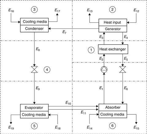
FIGURE 6.26 Availability flow balance of the absorption system.
Design of single-effect LiBr–water absorption systems
To perform estimations of equipment sizing and performance evaluation of a single-effect water-lithium bromide absorption cooler, basic assumptions and input values must be considered. With reference to Figures 6.23–6.25, usually the following assumptions are made:
1. The steady-state refrigerant is pure water.
2. There are no pressure changes except through the flow restrictors and the pump.
3. At points 1, 4, 8, and 11, there is only saturated liquid.
4. At point 10, there is only saturated vapor.
5. Flow restrictors are adiabatic.
7. There are no jacket heat losses.
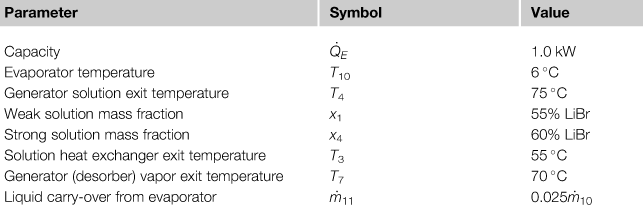
A small 1 kW unit was designed and constructed by co-workers and the author (Florides et al., 2003). To design such a system, the design (or input) parameters must be specified. The parameters considered for the 1 kW unit are listed in Table 6.3.
Table 6.3
Design Parameters for the Single-Effect Water–Lithium Bromide Absorption Cooler
The equations of Table 6.2 can be used to estimate the energy, mass concentrations, and mass balance of a LiBr–H2O system. Some details are given in the following paragraphs so the reader will understand the procedure required to design such a system.
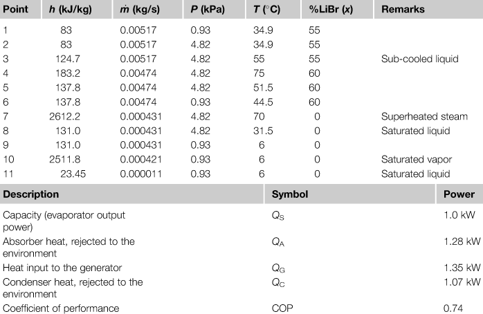
Since, in the evaporator, the refrigerant is a saturated water vapor and the temperature (T10) is 6 °C, the saturation pressure at point 10 is 0.9346 kPa (from steam tables) and the enthalpy is 2511.8 kJ/kg. Since, at point 11, the refrigerant is a saturated liquid, its enthalpy is 23.45 kJ/kg. The enthalpy at point 9 is determined from the throttling process applied to the refrigerant flow restrictor, which yields h9 = h8. To determine h8, the pressure at this point must be determined. Since, at point 4, the solution mass fraction is 60% LiBr and the temperature at the saturated state is assumed to be 75 °C, the LiBr–water charts (see ASHRAE, 2005) give a saturation pressure of 4.82 kPa and h4 = 183.2 kJ/kg. Considering that the pressure at point 4 is the same as in 8, h8 = h9 = 131.0 kJ/kg (steam tables). Once the enthalpy values at all ports connected to the evaporator are known, mass and energy balances, shown in Table 6.2, can be applied to give the mass flow of the refrigerant and the evaporator heat transfer rate.
The heat transfer rate in the absorber can be determined from the enthalpy values at each of the connected state points. At point 1, the enthalpy is determined from the input mass fraction (55%) and the assumption that the state is a saturated liquid at the same pressure as the evaporator (0.9346 kPa). The enthalpy value at point 6 is determined from the throttling model, which gives h6 = h5.
The enthalpy at point 5 is not known but can be determined from the energy balance on the solution heat exchanger, assuming an adiabatic shell, as follows:
![]() (6.81)
(6.81)
The temperature at point 3 is an input value (55 °C) and since the mass fraction for points 1 to 3 is the same, the enthalpy at this point is determined as 124.7 kJ/kg. Actually, the state at point 3 may be a sub-cooled liquid. However, at the conditions of interest, the pressure has an insignificant effect on the enthalpy of the sub-cooled liquid and the saturated value at the same temperature and mass fraction can be an adequate approximation.
The enthalpy at state 2 can be determined from the equation for the pump shown in Table 6.2 or from an isentropic pump model. The minimum work input (w) can therefore be obtained from:
![]() (6.82)
(6.82)
In Eq. (6.82), it is assumed that the specific volume (ν, m3/kg) of the liquid solution does not change appreciably from point 1 to point 2. The specific volume of the liquid solution can be obtained from a curve fit of the density (Lee et al., 1990) and noting that ν = 1/ρ:
![]() (6.83)
(6.83)
This equation is valid for 0 < T < 200 °C and 20 < x < 65%.
The temperature at point 5 can be determined from the enthalpy value. The enthalpy at point 7 can be determined, since the temperature at this point is an input value. In general, the state at point 7 is superheated water vapor and the enthalpy can be determined once the pressure and temperature are known.
A summary of the conditions at various parts of the unit is shown in Table 6.4; the point numbers are as shown in Figure 6.23.
Table 6.4
LiBr–Water Absorption Refrigeration System Calculations Based on a Generator Temperature of 75 °C and a Solution Heat Exchanger Exit Temperature of 55 °C
Ammonia–water absorption systems
Contrary to compression refrigeration machines, which need high-quality electric energy to run, ammonia–water absorption refrigeration machines use low-quality thermal energy. Moreover, because the temperature of the heat source does not usually need to be so high (80–170 °C), the waste heat from many processes can be used to power absorption refrigeration machines. In addition, an ammonia–water refrigeration system uses natural substances, which do not cause ozone depletion as working fluids. For all these reasons, this technology has been classified as environmentally friendly (Herold et al., 1996; Alefeld and Radermacher, 1994).
The NH3–H2O system is more complicated than the LiBr–H2O system, since it needs a rectifying column to assure that no water vapor enters the evaporator, where it could freeze. The NH3–H2O system requires generator temperatures in the range of 125–170 °C with an air-cooled absorber and condenser and 80–120 °C when water cooling is used. These temperatures cannot be obtained with flat-plate collectors. The coefficient of performance, which is defined as the ratio of the cooling effect to the heat input, is between 0.6 and 0.7.
The single-stage ammonia–water absorption refrigeration system cycle consists of four main components—condenser, evaporator, absorber, and generator—as shown in Figure 6.27. Other auxiliary components include expansion valves, pump, rectifier, and heat exchanger. Low-pressure, weak solution is pumped from the absorber to the generator through the solution heat exchanger operating at high pressure. The generator separates the binary solution of water and ammonia by causing the ammonia to vaporize and the rectifier purifies the ammonia vapor. High-pressure ammonia gas is passed through the expansion valve to the evaporator as low-pressure liquid ammonia. The high-pressure transport fluid (water) from the generator is returned to the absorber through the solution heat exchanger and the expansion valve. The low-pressure liquid ammonia in the evaporator is used to cool the space to be refrigerated. During the cooling process, the liquid ammonia vaporizes and the transport fluid (water) absorbs the vapor to form a strong ammonia solution in the absorber (ASHRAE, 2005; Herold et al., 1996).
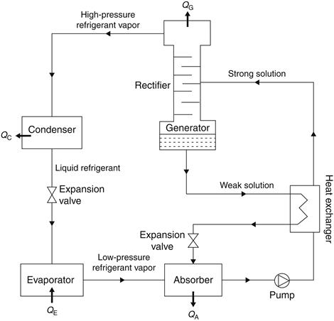
FIGURE 6.27 Schematic of the ammonia–water refrigeration system cycle.
In some cases, a condensate pre-cooler is used to evaporate a significant amount of the liquid phase. This is, in fact, a heat exchanger located before the expansion valve, in which the low-pressure refrigerant vapor passes to remove some of the heat of the high-pressure and relatively high-temperature (∼40 °C) ammonia. Therefore, some liquid evaporates and the vapor stream is heated, so there is additional cooling capacity available to further sub-cool the liquid stream, which increases the COP.
Leave a Reply