Systems for space heating are very similar to those for water heating, described in the previous chapter; and because the same considerations apply to both systems for combination with an auxiliary source, array design, over-temperature and freezing, controls, and so on, these will not be repeated. The most common heat transfer fluids are water, water and antifreeze mixtures, and air. The load is the building to be heated or cooled. Although it is technically possible to construct a solar heating or cooling system that can satisfy fully the design load, such a system would be non-viable, since it would be oversized most of the time. The size of the solar system may be determined by a life-cycle cost analysis described in Chapter 12.
Active solar space heating systems use collectors to heat a fluid, storage units to store solar energy until needed, and distribution equipment to provide the solar energy to the heated spaces in a controlled manner. Additionally, a complete system includes pumps or fans for transferring the energy to storage or to the load; these require a continuous availability of non-renewable energy, generally in the form of electricity.
The load can be space cooling, heating, or a combination of these two with hot water supply. When it is combined with conventional heating equipment, solar heating provides the same levels of comfort, temperature stability, and reliability as conventional systems.
During daytime, the solar energy system absorbs solar radiation with collectors and conveys it to storage using a suitable fluid. As the building requires heat, this is obtained from storage. Control of the solar energy system is exercised by differential temperature controllers, described in Chapter 5, Section 5.5. In locations where freezing conditions may occur, a low-temperature sensor is installed on the collector to control the solar pump when a preset temperature is reached. This process wastes some stored heat, but it prevents costly damage to the solar collectors. Alternatively, systems described in the previous chapter, such as the drain-down and drain-back, can be used, depending on whether the system is closed or open.
Solar cooling of buildings is an attractive idea because the cooling loads and availability of solar radiation are in phase. Additionally, the combination of solar cooling and heating greatly improves the use factors of collectors compared to heating alone. Solar air conditioning can be accomplished mainly by two types of systems: absorption cycles and adsorption (desiccant) cycles. Some of these cycles are also used in solar refrigeration systems. It should be noted that the same solar collectors are used for both space-heating and cooling systems when both are present.
A review of the various solar heating and cooling systems is presented by Hahne (1996) and a review of solar and low-energy cooling technologies is presented by Florides et al. (2002a).
6.3.1 Space heating and service hot water
Depending on the conditions that exist in a system at a particular time, the solar systems usually have five basic modes of operation:
1. When solar energy is available and heat is not required in the building, solar energy is added to storage.
2. When solar energy is available and heat is required in the building, solar energy is used to supply the building load demand.
3. When solar energy is not available, heat is required in the building, and the storage unit has stored energy, the stored energy is used to supply the building load demand.
4. When solar energy is not available, heat is required in the building, and the storage unit has been depleted, auxiliary energy is used to supply the building load demand.
5. When the storage unit is fully heated, there are no loads to meet, and the collector is absorbing heat, solar energy is discarded.
This last mode is achieved through the operation of pressure relief valves, or in the case of air collectors where the stagnant temperature is not detrimental to the collector materials, the flow of air is turned off; thus the collector temperature rises until the absorbed energy is dissipated by thermal losses.
In addition to the operation modes just outlined, the solar energy system is usually used to provide domestic hot water. These modes are usually controlled by thermostats. So, depending on the load of each service, heating, cooling, or hot water, the thermostat that is not satisfied gives a signal to operate a pump, provided that the collector temperature is higher than that of storage, as explained in Chapter 5, Section 5.5. Therefore, by using the thermostats, it is possible to combine modes and operate in more than one mode at a time. Some systems do not allow direct heating from a solar collector to heat the building but always transfer heat from collector to storage, whenever this is available, and from storage to load, whenever this is needed.
In Europe, solar heating systems for combined space and water heating are known as combisystems, and the storage tanks of these systems are called combistores. Many of these combistore tanks have one or more heat exchangers immersed directly in the storage fluid. The immersed heat exchangers are used for various functions, including charging via solar collectors or a boiler and discharging for domestic hot water and space heating uses.
For combisystems, the heat store is the key component, since it is used as short-term storage for solar energy and as buffer storage for the fuel or wood boiler. The storage medium used in solar combistores is usually the water of the space-heating loop and not the tap water used in conventional solar domestic hot water stores. The tap water is heated on demand by passing through a heat exchanger, which can be placed either inside or outside the tank containing the water of the heating loop. When the heat exchanger is in direct contact with the storage medium, the maximum tap water temperature at the start of the draw-off is similar to the temperature of the water inside the store. The tap water volume inside the heat exchanger can vary from a few liters for immersed heat exchangers to several hundred liters for tank-in-tank stores.
Three typical combistores are shown in Figure 6.10. In the first, shown in Figure 6.10(a), an immersed heat exchanger is used, mounted on the whole inside surface of the mantle and top of the store. In the second store, shown in Figure 6.10(b), the preparation of hot water is based on a natural circulation (thermosiphoning) heat exchanger, which is mounted in the upper part of the store. The third one, shown in Figure 6.10(c), is the tank-in-tank case, where a conical hot water tank is placed inside the main tank, as shown, its bottom part reaching nearly the bottom of the store. Typical tap water volumes in heat exchanger are 15, 10, and 150–200 l for the three tanks, respectively (Druck and Hahne, 1998).
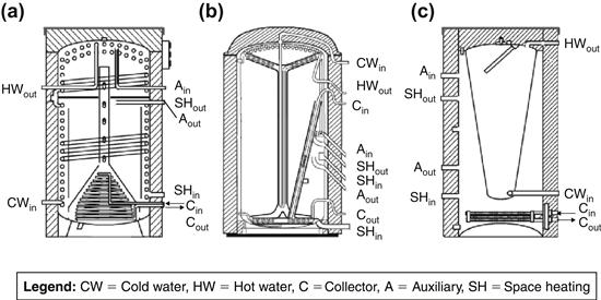
FIGURE 6.10 (a) Immersed heat exchanger, (b) natural circulation heat exchanger, (c) tank-in-tank. Adapted from Druck and Hahne (1998).
In the initial stages of design of a solar space-heating system, a number of factors need to be considered. Among the first ones is whether the system will be direct or indirect and whether a different fluid will be used in the solar system and the heat delivery system. This is decided primarily from the possibility of freezing conditions at the site of interest. Generally speaking, the designer must be aware that the presence of a heat exchanger in a system imposes a penalty of 5–10% in the effective energy delivered to the system. This is usually translated as an extra percentage of collector area to allow the system to deliver the same quantity of energy as a system with no heat exchanger.
Another important parameter to consider is the time matching of the load and solar energy input. Over the annual seasonal cycle, energy requirements of a building are not constant. For the Northern Hemisphere, heating requirements start around October, the maximum heating load is during January or February, and the heating season ends around the end of April. Depending on the latitude, cooling requirements start in May, the maximum is about the end of July, and the cooling season ends around the end of September. The domestic hot water requirements are almost constant, with small variations due to variations in water supply temperature. Although it is possible to design a system that could cover the total thermal load requirements of a building, a very large collector area and storage would be required. Therefore, such a system would not be economically viable, because the system would be oversized for most of the year, i.e., it will collect energy that it could not use for most of the time.
As can be understood from above, the load is not constant and varies throughout the year and a space-heating system could be inoperative during many months of the year, which could create overheating problems in the solar collectors during summertime. To avoid this problem, a solar space-heating system needs to be combined with solar space cooling so as to utilize fully the solar system throughout the year. Solar heating systems are examined in this section, whereas solar cooling systems are examined in Section 6.4.
A space-heating system can use either air or liquid collectors, but the energy delivery system may use the same medium or a different one. Usually air systems use air for the collection, storage, and delivery system; but liquid systems may use water or water plus antifreeze solution for the collection circuit, water for storage, and water (e.g. a floor heating system) or air (e.g. a water-to-air heat exchanger and air handling unit) for the heat delivery.
Many variations of systems are used for both solar space heating and service hot water production. The basic configuration is similar to the solar water heating systems outlined in Sections 5.2.1–5.2.3. When used for both space and hot water production, these systems allow independent control of the solar collector-storage and storage-auxiliary-load loops, because solar-heated water can be added to storage at the same time that hot water is removed from storage to meet the building loads. Usually, a bypass is provided around the storage tank to avoid heating the storage tank, which can be of considerable size, with auxiliary energy. This is examined in more detail in Section 6.3.4.
6.3.2 Air systems
A schematic of a basic solar air-heating system with a pebble bed storage unit and auxiliary heating source is shown in Figure 6.11. In this case, the various operation modes are achieved by the use of the dampers shown. Usually, in air systems, it is not practical to have simultaneous addition and removal of energy from the storage. If the energy supplied from the collector or storage is inadequate to meet the load, auxiliary energy can be used to top up the air temperature to cover the building load. As shown in Figure 6.11, it is also possible to bypass the collector and storage unit when there is no sunshine and the storage tank is completely depleted, and use the auxiliary alone to provide the required heat. A more detailed schematic of an air space-heating system incorporating a subsystem for the preparation of domestic hot water is shown in Figure 6.12. For the preparation of hot water, an air-to-water heat exchanger is used. Usually a preheat tank is used as shown. Details of controls are also shown in Figure 6.12. Furthermore, the system can use air collectors and a hydronic space-heating system in an arrangement similar to the water-heating air system described in Section 5.2.3 and shown in Figure 5.14.
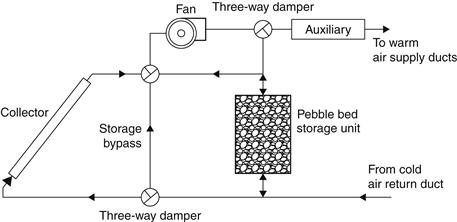
FIGURE 6.11 Schematic of basic hot-air system.
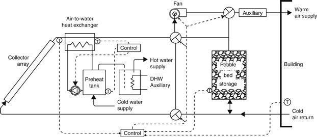
FIGURE 6.12 Detailed schematic of a solar air-heating system.
The advantages of using air as a heat transfer fluid are outlined in the section on water-heating air systems (Section 5.2.3). Other advantages include the high degree of stratification that occurs in the pebble bed, which leads to lower collector inlet temperatures. Additionally, the working fluid is air, and warm-air-heating systems are common in the building services industry. Control equipment that can be applied to these systems is also readily available from the building services industry. Amongst the disadvantages of water-heating air systems (see Section 5.2.3) is the difficulty of adding solar air conditioning to the system, higher storage costs, and noisier operation. Another disadvantage is that air collectors are operated at lower fluid capacitance rates and thus with lower values of FR than the liquid-heating collectors.
Usually, air-heating collectors used in space-heating systems are operated at fixed air flow rates; therefore the outlet temperature varies through the day. It is also possible to operate the collectors at a fixed outlet temperature by varying the flow rate. When flow rates are low, however, they result in reduced FR and therefore reduced collector performance.
6.3.3 Water systems
Many varieties of systems can be used for both solar space heating and domestic hot water production. The basic configurations are similar to the solar water heating systems outlined in Sections 5.2.1 and 5.2.2. When used for both space heating and hot water production and because solar-heated water can be added to storage at the same time that hot water is removed from storage to meet building loads, the system allows independent control of the solar collector-storage and storage-auxiliary-load loops. Usually, a bypass is provided around the storage tank to avoid heating the storage tank, which can be of considerable size, with auxiliary energy.
A schematic diagram of a solar heating and hot water system is shown in Figure 6.13. Control of the solar heating system is based on two thermostats: the collector-storage temperature differential and the room temperature. The collector operates with a differential thermostat, as explained in Chapter 5, Section 5.5. When the room thermostat senses a low temperature, the load pump is activated, drawing the heated water from the main storage tank to meet the demand. If the energy stored in the tank cannot meet the load demand, the thermostat activates the auxiliary heater to supply the balance of the heating requirements. Usually, the controller also operates the three-way valves shown in Figure 6.13 so that the flow is entirely through the auxiliary heater whenever the storage tank is depleted.
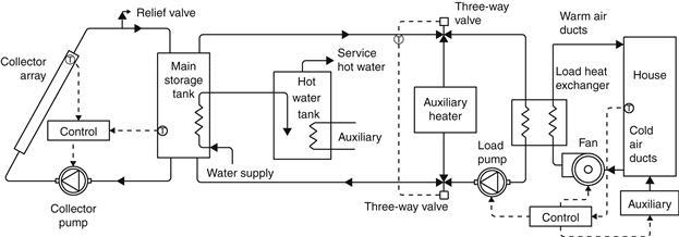
FIGURE 6.13 Schematic diagram of a solar space-heating and hot water system.
The solar heating system design shown in Figure 6.13 is suitable for use in non-freezing climates. To use such a system in locations where freezing is possible, provisions for complete and dependable drainage of the collector must be made. This can be done with an automatic discharge valve, activated by the ambient air temperature, and an air vent. This is the usual arrangement of the drain-down system, described in Chapter 5, Section 5.2.1, in which the collector water is drained out of the system to waste. Alternatively, a drain-back system, described in Chapter 5, Section 5.2.2, can be used, in which the collector water is drained back to the storage whenever the solar pump stops. When this system drains, air enters the collector through a vent.
If the climate is characterized by frequent sub-freezing temperatures, positive freeze protection with the use of an antifreeze solution in a closed collector loop is necessary. A detailed schematic of such a liquid-based system is shown in Figure 6.14. A collector heat exchanger is used between the collector and the storage tank, which allows the use of antifreeze solutions to the collector circuit. The usual solution is water plus glycol. Relief valves are also required to dump excess energy if over-temperature conditions exists. To “top off” the energy available from the solar energy system, auxiliary energy is required. It should be noted that the connections to the storage tank should be done in such a way as to enhance stratification, i.e., cold streams to be connected at the bottom and hot streams at the top. In this way, cooler water or fluid is supplied to the collectors to maintain the best possible efficiency. In this type of system, the auxiliary energy is never used directly in the solar storage tank. This is treated in more detail in the next section.
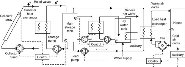
FIGURE 6.14 Detailed schematic diagram of a solar space-heating and hot water system with antifreeze solution.
The use of a heat exchanger between the collector heat transfer fluid and the storage water imposes a temperature differential across the two sides, and thus the storage tank temperature is lowered. This is a disadvantage for system performance, as described in Chapter 5, Section 5.4.2; however, this system design is preferred in climates with frequent freezing conditions, to avoid the danger of malfunction in a self-draining system.
A load heat exchanger is also required, as shown in Figure 6.14, to transfer energy from the storage tank to the heated spaces. It should be noted that the load heat exchanger must be adequately sized to avoid excessive temperature drops with a corresponding increase in the tank and collector temperatures.
The advantages of liquid heating systems are the high collector FR, small storage volume requirement, and relatively easy combination with an absorption air conditioner for cooling (see Section 6.4.2).
The analysis of these systems is similar to the water heating systems presented in Chapter 5. When both space heating and hot water are considered, the rate of the energy removed from the storage tank to load (Ql) in Eq. (5.31) is replaced by Qls, the space load supplied by solar energy through the load heat exchanger, and the term Qlw, representing the domestic water heating load supplied through the domestic water heat exchanger, as shown in the following equation, which neglects stratification in the storage tank:
![]() (6.60)
(6.60)
The terms Qu and Qtl can be obtained from Eqs (4.2) and (5.32), respectively.
The space-heating load, Qhl, can be estimated from the following equation (positive values only):
![]() (6.61)
(6.61)
(UA)l = space loss coefficient and area product, given by Eq. (6.25).
The maximum rate of heat transferred across the load heat exchanger, Qle(max), is given by:
![]() (6.62)
(6.62)
εl = load heat exchanger effectiveness;
![]() = air loop mass flow rate and specific heat product (W/K); and
= air loop mass flow rate and specific heat product (W/K); and
Ts = storage tank temperature (°C).
It should be noted that, in Eq. (6.62), the air side capacitance rate of the water-to-air heat exchanger is considered to be the minimum because the cp (∼1.05 kJ/kg °C) of air is much lower than the cp of water (∼4.18 kJ/kg °C).
The space load, Qls, is then given by (positive values only):
![]() (6.63)
(6.63)
The domestic water heating load, Qw, can be estimated from:
![]() (6.64)
(6.64)
![]() = domestic water mass flow rate and specific heat product (W/K);
= domestic water mass flow rate and specific heat product (W/K);
Tw = required hot water temperature, usually 60 °C; and
Tmu = make-up water temperature from mains (°C).
The domestic water heating load supplied by solar energy through the domestic water heat exchanger, Qlw, of effectiveness εw, can be estimated from:
![]() (6.65)
(6.65)
Finally, the auxiliary energy required, Qaux, to cover the domestic water heating and space loads is given by (positive values only):
![]() (6.66)
(6.66)
where the auxiliary energy required to cover the domestic water heating load, Qaux,w, is given by (positive values only):
EXAMPLE 6.7
A space is maintained at a room temperature TR = 21 °C and has a (UA)l = 2500 W/°C. The ambient temperature is 1 °C and the storage tank temperature is 80 °C. Estimate the space load, domestic water heating load, and auxiliary energy required if the following apply:
1. Heat exchanger effectiveness = 0.7.
2. Flow rate of air side of heat exchanger = 1.1 kg/s.
3. Specific heat of air = 1.05 kJ/hg °C.
4. Environmental temperature at the space where storage tank is located = 15 °C.
5. UA of storage tank = 2.5 W/°C.
6. Mass flow rate of domestic water = 0.2 kg/s.
7. Required domestic water temperature = 60 °C.
8. Make-up water temperature = 12 °C.
Solution
The space-heating load, Qhl, can be estimated from Eq. (6.61):

The maximum rate of heat transferred across the load heat exchanger, Qle(max), is given by Eq. (6.62):

The space load, Qls, is then given by Eq. (6.63):

The storage tank losses are estimated from Eq. (5.32):

The domestic water heating load, Qw, can be estimated from Eq. (6.64):

The rate of auxiliary energy required to cover the domestic water heating load, Qaux,w, is given by Eq. (6.67):

The rate of auxiliary energy required, Qaux, to cover the domestic water heating and space loads is given by Eq. (6.66):

It should be noted that, in all cases where a heat exchanger is used, the penalty of using this heat exchanger can be estimated according to Eq. (5.57), as indicated by the following example.
EXAMPLE 6.8
A space-heating and hot water system has a collector with FRUL = 5.71 W/m2 °C and area of 16 m2. What is the ratio ![]() if the flow rate of antifreeze is 0.012 kg/s m2 and water is 0.018 kg/s m2 in a collector–storage heat exchanger of effectiveness equal to 0.63, and the cp of water is 4180 J/kg °C and of antifreeze is 3350 J/kg °C?
if the flow rate of antifreeze is 0.012 kg/s m2 and water is 0.018 kg/s m2 in a collector–storage heat exchanger of effectiveness equal to 0.63, and the cp of water is 4180 J/kg °C and of antifreeze is 3350 J/kg °C?
Solution
First, the capacitance rates for the collector and tank sides are required, given by:


Therefore, the minimum:

From Eq. (5.57), we get:

6.3.4 Location of auxiliary heater
One important consideration concerning the storage tank is the decision as to the best location for the auxiliary heater. This is especially important for solar space-heating systems because larger amounts of auxiliary energy are usually required and storage tank sizes are large. For maximum utilization of the energy supplied by an auxiliary source, the location of this energy input should be at the load, not at the storage tank. The supply of auxiliary energy at the storage tank will undoubtedly increase the temperature of fluid entering the collector, resulting in lower collector efficiency. When a water-based solar energy system is used in conjunction with a warm-air space-heating system, the most economical means of auxiliary energy supply is by the use of a fossil fuel-fired boiler. In case of bad weather, the boiler can take over the entire heating load.
When a water-based solar energy system is used in conjunction with a water space-heating system or to supply the heated water to an absorption air-conditioning unit, the auxiliary heater can be located in the storage-load loop, either in series or in parallel with the storage, as illustrated in Figure 6.15. When auxiliary energy is employed to boost the temperature of solar energy heated water, as shown in Figure 6.15(a), maximum utilization of stored solar energy is achieved. This way of connecting the auxiliary supply, however, also has the tendency to boost the storage tank temperature because water returning from the load may be at a higher temperature than the storage tank. Increasing the storage temperature using auxiliary energy has the undesirable effect of lowering the collector effectiveness, in addition to diverting the storage capacity to the storage of auxiliary energy instead of solar energy. This, however, depends on the operating temperature of the heating system. Therefore, a low-temperature system is required. This can be achieved with a water-to-air heat exchanger, either centrally with an air-handling unit or in a distributed way with individual fan coil units in each room to be heated. This system has the advantage of connecting easily with space-cooling systems, as for example with an absorption system (see Section 6.4). By using this type of system, solar energy can be used more effectively, because a high-temperature system would imply that the hot water storage remains at high temperature, so solar collectors would work at lower efficiency.
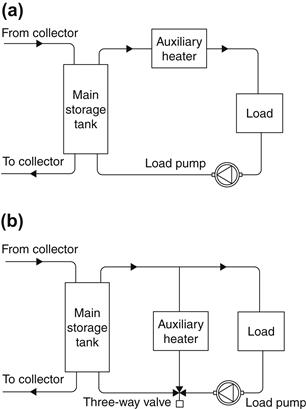
FIGURE 6.15 Auxiliary energy supply in water-based systems. (a) In series with load. (b) Parallel with load.
Another possibility is to use an underfloor heating or an all-water system employing traditional heating radiators. In the latter case, provisions need to be made during the design stage to operate the system at low temperatures, which implies the use of bigger radiators. Such a system is also suitable for retrofit applications.
Figure 6.15(b) illustrates an arrangement that makes it possible to isolate the auxiliary heating circuit from the storage tank. Solar-heated storage water is used exclusively to meet load demands when its temperature is adequate. When the storage temperature drops below the required level, circulation through the storage tank is discontinued and hot water from the auxiliary heater is used exclusively to meet space-heating needs. This way of connecting the auxiliary supply avoids the undesirable increase in storage water temperature by auxiliary energy. However, it has the disadvantage that a stored solar energy at lower temperatures is not fully utilized, and this energy may be lost from the storage (through jacket losses). The same requirements for a low-temperature system apply here as well in order to be able to extract as much energy as possible from the storage tank.
6.3.5 Heat pump systems
Active solar energy systems can also be combined with heat pumps for domestic water heating or space heating. In residential heating, the solar energy system can be used in parallel with a heat pump, which supplies auxiliary energy when the sun is not available. Additionally, for domestic water systems requiring high water temperatures, a heat pump can be placed in series with the solar storage tank.
A heat pump is a device that pumps heat from a low-temperature source to a higher-temperature sink. Heat pumps are usually vapor compression refrigeration machines, where the evaporator can take heat into the system at low temperatures and the condenser can reject heat from the system at high temperatures. In the heating mode, a heat pump delivers thermal energy from the condenser for space heating and can be combined with solar heating. In the cooling mode, the evaporator extracts heat from the air to be conditioned and rejects heat from the condenser to the atmosphere, with solar energy not contributing to the energy for cooling. The performance characteristics of an integral type of solar-assisted heat pump are given by Huang and Chyng (2001).
Heat pumps use mechanical energy to transfer thermal energy from a source at a lower temperature to a sink at a higher temperature. Electrically driven heat pump-heating systems have two advantages compared to electric resistance heating or expensive fuels. The first one, as was seen in Chapter 5, Section 5.2.4, is that the heat pump’s ratio of heating performance to electrical energy (COP) is high enough to yield 9–15 MJ of heat for each kWh of energy supplied to the compressor, which saves on the purchase of energy. The second is the usefulness for air conditioning in the summer. Water-to-air heat pumps, which use solar-heated water from the storage tank as the evaporator energy source, are an alternative auxiliary heat source. Use of water involves freezing problems, which need to be taken into consideration.
Heat pumps have been used in combination with solar systems in residential and commercial applications. The additional complexity imposed by such a system and extra cost are offset by the high coefficient of performance and the lower operating temperature of the collector subsystem. A schematic of a common residential type heat pump system is shown in Figure 6.16. During favorable weather conditions, it is possible with this arrangement to have solar energy delivered directly to the forced air system while the heat pump is kept off.
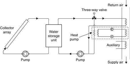
FIGURE 6.16 Schematic diagram of a domestic water-to-air heat pump system (series arrangement).
The arrangement shown in Figure 6.16 is a series configuration, where the heat pump evaporator is supplied with energy from the solar energy system, called a water-to-air heat pump. As can be seen, energy from the collector system is supplied directly to the building when the temperature of the water in the storage temperature is high. When the storage tank temperature cannot satisfy the load, the heat pump is operated; thus it benefits from the relatively high temperature of the solar energy system, which is higher than the ambient and this increases the heat pump’s COP. A parallel arrangement is also possible, where the heat pump serves as an independent auxiliary energy source for the solar energy system, as shown in Figure 6.17. In this case, a water-to-water heat pump is used.
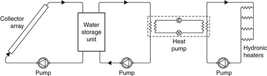
FIGURE 6.17 Schematic diagram of a domestic water-to-water heat pump system (parallel arrangement).
The series configuration is usually preferred because it allows all the solar collected power to be used, leaving the tank at a low temperature, which allows the solar energy system to work more effectively the next day. Additionally, the heat pump performance is higher with high evaporator temperatures. An added advantage of this system is that the solar energy system is conventional, using liquid collectors and a water storage tank. A dual-source heat pump can also be used, in which another form of renewable energy, such as a pellets boiler, can be used when the storage tank is completely depleted. In such a case, a control system selects the heat source to use for the best heat pump COP, i.e., it selects the higher of the two heat sources. Another possible design is to use an air solar heating system and an air-to-air heat pump.
Leave a Reply