Parabolic trough collectors are frequently employed for solar steam generation because relatively high temperatures can be obtained without serious degradation in the collector efficiency. Low-temperature steam can be used in industrial applications, in sterilization, and for powering desalination evaporators.
Three methods have been employed to generate steam using parabolic trough collectors (Kalogirou et al., 1997):
1. The steam–flash concept, in which pressurized water is heated in the collector and flashed to steam in a separate vessel.
2. The direct or in situ concept, in which two-phase flow is allowed in the collector receiver so that steam is generated directly.
3. The unfired boiler concept, in which a heat transfer fluid is circulated through the collector and steam is generated via heat exchange in an unfired boiler.
All three steam generation systems have advantages and disadvantages. These are examined in the following section.
7.2.1 Steam generation methods
The steam–flash system is shown schematically in Figure 7.5. In this system, water, pressurized to prevent boiling, is circulated through the collector and flashed across a throttling valve into a flash vessel. Treated feed-water input maintains the level in the flash vessel and the sub-cooled liquid is recirculated through the collector.
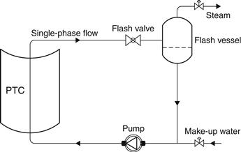
FIGURE 7.5 The steam–flash steam generation concept.
The in situ boiling concept, shown in Figure 7.6, uses a similar system configuration with no flash valve. Sub-cooled water is heated to boiling and steam forms directly in the receiver tube. According to Hurtado and Kast (1984), capital costs associated with direct steam and flash–steam systems are approximately the same.
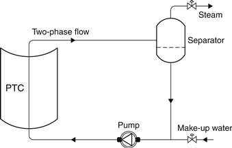
FIGURE 7.6 The direct steam generation concept.
Although both systems use water, a superior heat transport fluid, the in situ boiling system is more advantageous. The flash system uses a sensible heat change in the working fluid, which makes the temperature differential across the collector relatively high. The rapid increase in water vapor pressure with temperature requires a corresponding increase in system operating pressure to prevent boiling. Increased operating temperatures reduce the thermal efficiency of the solar collector. Increased pressures within the system require a more robust design of collector components, such as receivers and piping. The differential pressure over the delivered steam pressure required to prevent boiling is supplied by the circulation pump and is irreversibly dissipated across the flash valve. When boiling occurs in the collectors, as in an in situ boiler, the system pressure drop and, consequently, electrical power consumption are greatly reduced. In addition, the latent heat transfer process minimizes the temperature rise across the solar collector. Disadvantages of in situ boiling are the possibility of a number of stability problems (Peterson and Keneth, 1982) and the fact that, even with a very good feed-water treatment system, scaling in the receiver is unavoidable. In multiple row collector arrays, the occurrence of flow instabilities could result in loss of flow in the affected row. This in turn could result in tube dry-out, with consequent damage to the receiver selective coating. No significant instabilities were reported, however, by Hurtado and Kast (1984) when experimentally testing a single-row 36 m system. Recently, once-through systems have been developed on a pilot scale for direct steam generation in which parabolic trough collectors inclined at 2–4° are used (Zarza et al., 1999).
A diagram of an unfired boiler system is shown in Figure 7.7. In this system, a heat transfer fluid is circulated through the collector, which is non-freezing and non-corrosive and in which system pressures are low and control is straightforward. These factors largely overcome the disadvantages of water systems and are the main reasons for the predominant use of heat transfer oil systems in current industrial steam-generating solar systems.
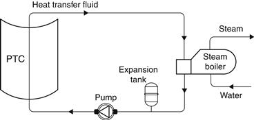
FIGURE 7.7 The unfired boiler steam generation concept.
The major disadvantage of the system results from the characteristics of the heat transfer fluid. These fluids are hard to contain, and most heat transfer fluids are flammable. Decomposition, when the fluids are exposed to air, can greatly reduce ignition point temperatures and leaks into certain types of insulation can cause combustion at temperatures that are considerably lower than measured self-ignition temperatures. Heat transfer fluids are also relatively expensive and present a potential pollution problem that makes them unsuitable for food industry applications (Murphy and Keneth, 1982). Heat transfer fluids have much poorer heat transfer characteristics than water. They are more viscous at ambient temperatures, are less dense, and have lower specific heats and thermal conductivities than water. These characteristics mean that higher flow rates, higher collector differential temperatures, and greater pumping power are required to obtain the equivalent quantity of energy transport when compared with a system using water. In addition, heat transfer coefficients are lower, so there is a larger temperature differential between the receiver tube and the collector fluid. Higher temperatures are also necessary to achieve cost-effective heat exchange. These effects result in reduced collector efficiency.
It should be noted that, for every application, a suitable system has to be selected by taking into consideration all these factors and constraints.
7.2.2 Flash vessel design
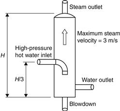
To separate steam at lower pressure, a flash vessel is used. This is a vertical vessel, as shown in Figure 7.8, with the inlet of high-pressure high-temperature water located at about one-third of the way up its height. The standard design of flash vessels requires that the diameter of the vessel is chosen so that the steam flows toward the top outlet connection at no more than about 3 m/s. This should ensure that any water droplets could fall through the steam in a contra-flow, to the bottom of the vessel. Adequate height above the inlet is necessary to ensure separation. The separation is also facilitated by having the inlet projecting downward into the vessel. The water connection is sized to minimize the pressure drop from the vessel to the pump inlet to avoid cavitation.
Leave a Reply