
Solar energy collectors are basically distinguished by their motion—stationary, single-axis tracking, and two-axis tracking—and the operating temperature. First, we’ll examine the stationary solar collectors. These collectors are permanently fixed in position and do not track the sun. Three main types of collectors fall into this category:
1. Flat-plate collector (FPC).
2. Stationary compound parabolic collector (CPC).
3. Evacuated tube collector (ETC).
3.1.1 Flat-plate collector (FPC)
A typical flat-plate solar collector is shown in Figure 3.1. When solar radiation passes through a transparent cover and impinges on the blackened absorber surface of high absorptivity, a large portion of this energy is absorbed by the plate and transferred to the transport medium in the fluid tubes, to be carried away for storage or use. The underside of the absorber plate and the two sides are well insulated to reduce conduction losses. The liquid tubes can be welded to the absorbing plate or they can be an integral part of the plate. The liquid tubes are connected at both ends by large-diameter header tubes. The header and riser collector is the typical design for flat-plate collectors. An alternative is the serpentine design shown in Figure 3.1(a). This collector does not present the potential problem of uneven flow distribution in the various riser tubes of the header and riser design, but serpentine collectors cannot work effectively in thermosiphon mode (natural circulation) and need a pump to circulate the heat transfer fluid (see Chapter 5). The absorber plate can be a single sheet on which all risers are fixed, or each riser can be fixed on a separate fin (see Figure 3.1(b)).
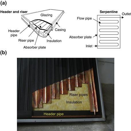
FIGURE 3.1 Typical flat-plate collector. (a) Pictorial view of a flat-plate collector. (b) Photograph of a cut header and riser flat-plate collector.
The transparent cover is used to reduce convection losses from the absorber plate through the restraint of the stagnant air layer between the absorber plate and the glass. It also reduces radiation losses from the collector because the glass is transparent to the shortwave radiation received by the sun, but it is nearly opaque to longwave thermal radiation emitted by the absorber plate (greenhouse effect).
The advantages of FPCs are that they are inexpensive to manufacture, they collect both beam and diffuse radiation, and they are permanently fixed in position, so no tracking of the sun is required. The collectors should be oriented directly toward the equator, facing south in the Northern Hemisphere and north in the Southern Hemisphere. The optimum tilt angle of the collector is equal to the latitude of the location, with angle variations of 10° to 15° more or less, depending on the application (Kalogirou, 2003). If the application is solar cooling, then the optimum angle is latitude −10° so that the sun will be perpendicular to the collector during summertime, when the energy will be mostly required. If the application is space heating, then the optimal angle is latitude +10°; whereas for annual hot water production, it is latitude +5°, to have relatively better performance during wintertime, when hot water is mostly required.
The main components of an FPC, as shown in Figure 3.2, are the following:
• Cover. One or more sheets of glass or other radiation-transmitting material.
• Heat removal fluid passageways. Tubes, fins, or passages that conduct or direct the heat transfer fluid from the inlet to the outlet.
• Absorber plate. Flat, corrugated, or grooved plates, to which the tubes, fins, or passages are attached. A typical attachment method is the embedded fixing shown in the detail of Figure 3.2. The plate is usually coated with a high-absorptance low-emittance layer.
• Headers or manifolds. Pipes and ducts to admit and discharge the fluid.
• Insulation. Used to minimize the heat loss from the back and sides of the collector.
• Container. The casing surrounds the aforementioned components and protects them from dust, moisture, and any other material.
Flat-plate collectors have been built in a wide variety of designs and from many different materials. They have been used to heat fluids such as water, water plus antifreeze additive, or air. Their major purpose is to collect as much solar energy as possible at the lowest possible total cost. The collector should also have a long effective life, despite the adverse effects of the sun’s ultraviolet radiation and corrosion and clogging because of acidity, alkalinity, or hardness of the heat transfer fluid, freezing of water, or deposition of dust or moisture on the glazing and breakage of the glazing from thermal expansion, hail, vandalism, or other causes. These causes can be minimized by the use of tempered glass.
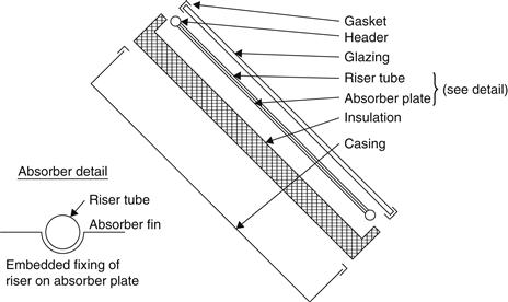
FIGURE 3.2 Exploded view of a flat-plate collector and absorber details.
In the following two sections, more details are given about the glazing and absorber plate materials. Most of these details also apply to other types of collectors. A third section refers to the collector construction and types of absorber configurations used.
Glazing materials
Glass has been widely used to glaze solar collectors because it can transmit as much as 90% of the incoming shortwave solar irradiation while transmitting virtually none of the longwave radiation emitted outward by the absorber plate (see Example 2.10). Window glass usually has high iron content and is not suitable for use in solar collectors. Glass with low iron content has a relatively high transmittance for solar radiation (approximately 0.85–0.90 at normal incidence), but its transmittance is essentially zero for the longwave thermal radiation (5.0–50 μm) emitted by sun-heated surfaces.
Plastic films and sheets also possess high shortwave transmittance, but because most usable varieties also have transmission bands in the middle of the thermal radiation spectrum, they may have longwave transmittances as high as 0.40. Additionally, plastics are generally limited in the temperatures they can sustain without deteriorating or undergoing dimensional changes. Only a few types of plastics can withstand the sun’s ultraviolet radiation for long periods. However, they are not broken by hail or stones, and in the form of thin films, they are completely flexible and have low mass.
The commercially available grades of window and greenhouse glass have normal incidence transmittances of about 0.87 and 0.85, respectively (ASHRAE, 2007). For direct radiation, the transmittance varies considerably with the angle of incidence.
Antireflective coatings and surface texture can improve transmission significantly. The effect of dirt and dust on collector glazing may be quite small, and the cleansing effect of an occasional rainfall is usually adequate to maintain the transmittance within 2–4% of its maximum value. Dust is collected mostly during summertime, when rainfall is less frequent, but due to the high magnitude of solar irradiation during this period, the dust protects the collector from overheating.
The glazing should admit as much solar irradiation as possible and reduce the upward loss of heat as much as possible. Although glass is virtually opaque to the longwave radiation emitted by the collector plates, absorption of that radiation causes an increase in the glass temperature and a loss of heat to the surrounding atmosphere through radiation and convection. These effects are analyzed in Section 3.3.
Various prototypes of transparently insulated FPCs and CPCs (see Section 3.1.2) were built and tested in the 1990s (Spate et al., 1999). Low-cost, high-temperature resistant transparent insulating (TI) materials have been developed so that the commercialization of these collectors becomes feasible. A prototype FPC covered by transparent insulation was developed and tested by Benz et al. (1998), and the efficiency of the collector was proven comparable with that of ETCs (see Section 3.1.3). However, no commercial collectors of this type are available on the market yet.
Collector absorbing plates
The collector plate absorbs as much of the irradiation as possible through the glazing, while losing as little heat as possible upward to the atmosphere and downward through the back of the casing. The collector plates transfer the retained heat to the transport fluid. To maximize the energy collection, the absorber of a collector should have a coating that has high absorptance for solar radiation (short wavelength) and a low emittance for re-radiation (long wavelength). Such a surface is referred to as a selective surface. The absorptance of the collector surface for shortwave solar radiation depends on the nature and color of the coating and on the incident angle. Usually black color is used, but various color coatings have been proposed by Tripanagnostopoulos et al. (2000a, b), Wazwaz et al. (2002), and Orel et al. (2002), mainly for aesthetic reasons.
By suitable electrolytic or chemical treatment, surfaces can be produced with high values of solar radiation absorptance (α) and low values of longwave emittance (ε). Essentially, typical selective surfaces consist of a thin upper layer, which is highly absorbent to shortwave solar radiation but relatively transparent to longwave thermal radiation, deposited on a surface that has a high reflectance and low emittance for longwave radiation. Selective surfaces are particularly important when the collector surface temperature is much higher than the ambient air temperature. The cheapest absorber coating is matte black paint; however, this is not selective, and the performance of a collector produced in this way is low, suitable for operating temperatures not more than 40 °C above ambient.
Many methods and materials or material combinations have been used to obtain the desired property of spectral selectivity. The various selective absorbers can be divided into the following categories:
1. Intrinsic materials or mass absorbers.
2. Tandem stacks and inverse tandem stacks.
3. Multilayer stacks (interference stacks).
4. Metal particles in a dielectric or metal matrix (cermets).
6. Quantum size effects (QSEs).
A comprehensive review of these absorbers is given by Yianoulis et al. (2012).
An energy-efficient solar collector should absorb incident solar radiation, convert it to thermal energy, and deliver the thermal energy to a heat transfer medium with minimum losses at each step. It is possible to use several design principles and physical mechanisms to create a selective solar-absorbing surface. Solar absorbers, referred to as tandem absorbers, are based on two layers with different optical properties. A semiconducting or dielectric coating with high solar absorptance and high infrared transmittance on top of a non-selective highly reflecting material such as metal constitutes one type of tandem absorber. Another alternative is to coat a non-selective highly absorbing material with a heat mirror that has a high solar transmittance and high infrared reflectance (Wackelgard et al., 2001).
Today, commercial solar absorbers are made by electroplating, anodization, evaporation, sputtering, and applying solar selective paints. Of the many types of selective coatings developed, the most widely used is black chrome. Much of the progress in recent years has been based on the implementation of vacuum techniques for the production of fin-type absorbers used in low-temperature applications. The chemical and electrochemical processes used for their commercialization were readily taken over from the metal finishing industry. The requirements of solar absorbers used in high-temperature applications, however—namely, extremely low thermal emittance and high-temperature stability—were difficult to fulfill with conventional wet processes. Therefore, large-scale sputter deposition was developed in the late 1970s. Nowadays, the vacuum techniques are mature, are characterized by low cost, and have the advantage of being less environmentally polluting than the wet processes.
When the roughness of a surface is smaller than the wavelength of light impinging on the surface it behaves like a mirror, and when it is larger it strongly absorbs the light of smaller wavelengths. High solar absorptance is enhanced by multiple reflections between pyramidal, dendrite, or porous microstructure. Sometimes the materials with this property are called wave front discriminating materials. Some surfaces can be made to appear rough to obtain spectral selectivity by optical trapping of solar radiation. Such a structure can be produced by etching with a proper acid, a procedure called surface texturing. Properly textured surfaces appear rough and absorb solar energy while appearing highly reflective and mirror-like to thermal energy. The orientation of a textured surface affects its optical properties and can improve the absorption and emissivity of a spectrally selective material.
Quantum size effects (QSEs) can be utilized to achieve high absorption in the short wavelength region while maintaining a low thermal IR emittance. These occur in ultrathin films and dots. The critical thickness for the QSE in a metal film is 2–3 nm, and for a degenerate semiconductor, 10–50 nm.
Collector construction
For fluid-heating collectors, passages must be integral with or firmly bonded to the absorber plate. A major problem is obtaining a good thermal bond between tubes and absorber plates without incurring excessive costs for labor or materials. The materials most used for collector plates are copper, aluminum, and stainless steel. UV-resistant plastic extrusions are used for low-temperature applications. If the entire collector area is in contact with the heat transfer fluid, the thermal conductance of the material is not important. The convective heat loss in a collector is relatively insensitive to the spacing between the absorber and the cover in the range of 15–40 mm. The back insulation of a flat-plate collector is made from fiberglass or a mineral fiber mat that will not outgas at elevated temperatures. Building-grade fiberglass is unsatisfactory because the binders evaporate at high temperature and then condense on the collector cover, blocking incoming solar radiation.
Figure 3.3 shows a number of absorber plate designs for solar water and air heaters that have been used with varying degrees of success. Figure 3.3(a) shows a bonded sheet design, in which the fluid passages are integral to the plate to ensure good thermal conduct between the metal and the fluid. Figure 3.3(b) and (c) show fluid heaters with tubes soldered, brazed, or otherwise fastened to upper or lower surfaces of sheets or strips of copper (see also the detail in Figure 3.2). Copper tubes are used most often because of their superior resistance to corrosion and high thermal conductivity.
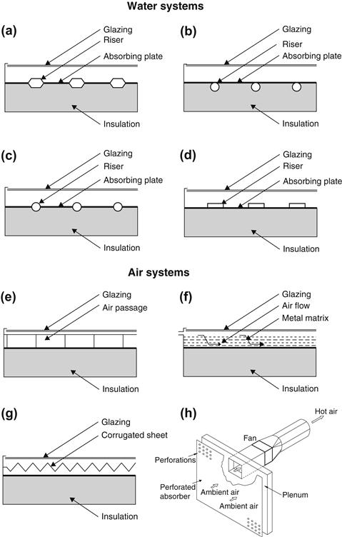
FIGURE 3.3 Various types of flat-plate solar collector absorber configurations for water and air.
Thermal cement, clips, clamps, or twisted wires have been tried in the search for low-cost bonding methods. Figure 3.3(d) shows the use of extruded rectangular tubing to obtain a larger heat transfer area between tube and plate. Mechanical pressure, thermal cement, or brazing may be used to make the assembly. Soft solder must be avoided because of the high plate temperature encountered at stagnation conditions, which could melt the solder.
The major difference between air- and water-based collectors is the need to design an absorber that overcomes the heat transfer penalty caused by lower heat transfer coefficients between air and the solar absorber. Air or other gases can be heated with flat-plate collectors, particularly if some type of extended surface (Figure 3.3(e)) is used to counteract the low heat transfer coefficients between metal and air (Kreider, 1982). Metal or fabric matrices (Figure 3.3(f)) (Kreider and Kreith, 1977; Kreider, 1982), thin corrugated metal sheets (Figure 3.3(g)), or porous absorbers may be used, with selective surfaces applied to the latter when a high level of performance is required. The principal requirement of these designs is a large contact area between the absorbing surface and the air. The thermal capacity of air is much lower than water, hence larger volume flow rates of air are required, resulting in higher pumping power.
Another type of air collector, shown in Figure 3.3(h), is the transpired. Transpired air collectors are quite simple structures used for heating purposes in buildings. This collector consists of a perforated blackened metal sheet which is placed at close distance in front of a south facing building wall. A fan forces ambient air to pass through the perforation holes, which is thus heated and distributed inside the building, as shown in Figure 3.3(h).
Reduction of heat loss from the absorber can be accomplished either by a selective surface to reduce radiative heat transfer or by suppressing convection. Francia (1961) showed that a honeycomb made of transparent material, placed in the airspace between the glazing and the absorber, was beneficial.
Another category of collectors, which is not shown in Figure 3.3, is the uncovered or unglazed solar collector. These are usually low-cost units that can offer cost-effective solar thermal energy in applications such as water preheating for domestic or industrial use, heating of swimming pools (Molineaux et al., 1994), space heating, and air heating for industrial or agricultural applications. Generally, these collectors are used in cases where the operating temperature of the collector is close to ambient. These collectors, usually called panel collectors, consist of a wide absorber sheet, made of plastic, containing closed-spaced fluid passages (see Figure 3.4). Materials used for plastic panel collectors include polypropylene, polyethylene, acrylic, and polycarbonate.
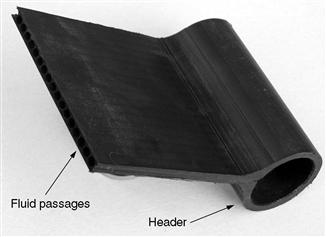
FIGURE 3.4 Photograph of a plastic collector absorber plate.
Flat-plate collectors are by far the most-used type of collector. Flat-plate collectors are usually employed for low-temperature applications, up to 80 °C, although some new types of collectors employing vacuum insulation or transparent insulation (TI) can achieve slightly higher values (Benz et al., 1998). Due to the introduction of highly selective coatings, actual standard flat-plate collectors can reach stagnation temperatures of more than 200 °C. With these collectors good efficiencies can be obtained up to temperatures of about 100 °C.
Lately some modern manufacturing techniques such as the use of laser and ultrasonic welding machines have been introduced by the industry that improve both the speed and the quality of welds. Both are used for welding of fins on risers, to improve heat conduction. The greatest advantage of the ultrasonic welding method is that the welding is performed at room temperature; therefore, deformation of the welded parts is avoided. However, this technique leaves a line across the absorber (at the welding point), which diminishes slightly the blackened collecting area. Laser welding provides a good seal between the absorber and the tubes without having the weak line associated with ultrasonic welding.
3.1.2 Compound parabolic collector (CPC)
Compound parabolic collectors (CPCs) are non-imaging concentrators. They have the capability of reflecting to the absorber all of the incident radiation within wide limits. Their potential as collectors of solar energy was pointed out by Winston (1974). The necessity of moving the concentrator to accommodate the changing solar orientation can be reduced by using a trough with two sections of a parabola facing each other, as shown in Figure 3.5.
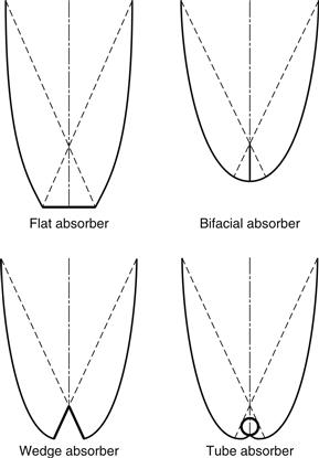
FIGURE 3.5 Various absorber types of CPCs.
Compound parabolic concentrators can accept incoming radiation over a relatively wide range of angles. By using multiple internal reflections, any radiation entering the aperture within the collector acceptance angle finds its way to the absorber surface located at the bottom of the collector. The absorber can take a variety of configurations. It can be flat, bifacial, wedge, or cylindrical, as shown in Figure 3.5. Details on the collector shape construction are presented in Section 3.6.1.
Two basic types of CPC collectors have been designed: symmetric and asymmetric. CPCs usually employ two main types of absorbers: the fin type with a pipe and tubular absorbers. The fin type can be flat, bifacial, or wedge, as shown in Figure 3.5 for the symmetric type, and can be single channel or multichannel.
CPCs should have a gap between the receiver and the reflector to prevent the reflector from acting as a fin conducting heat away from the absorber. Because the gap results in a loss of reflector area and a corresponding loss of performance, it should be kept small. This is more important for flat receivers.
For higher temperature applications a tracking CPC can be used. When tracking is used, this is very rough or intermittent, since the concentration ratio is usually small and radiation can be collected and concentrated by one or more reflections on the parabolic surfaces.
CPCs can be manufactured either as one unit with one opening and one receiver (see Figure 3.5) or as a panel (see Figure 3.6(a)). When constructed as a panel, the collector looks like an FPC, as shown in Figure 3.6(b).
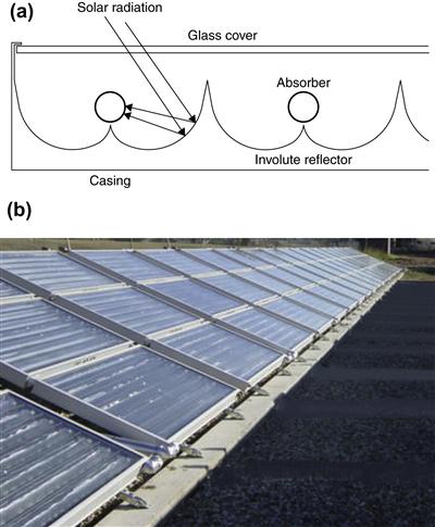
FIGURE 3.6 Panel CPC collector with cylindrical absorbers. (a) Schematic diagram. (b) Photo of a CPC panel collector installation.
Another category of CPC collectors is the asymmetric type. This can be combined with a reverse or upside down absorber plate configuration. Following the initial investigations on this type of system presented by Kienzlen et al. (1988), in these configurations radiation is directed on the underside of the plate by a stationary concentrator of the CPC shape shown in Figure 3.7(a). In this way, heat losses from the absorber are significantly reduced because the upper side of the plate is well insulated and the convective losses are reduced because the convective current is blocked by the plate itself. Another configuration is the inclined design shown in Figure 3.7(b). Compared with a flat-plate collector, these designs have lower optical efficiency due to the scattering losses in the reflector but better efficiency at higher temperatures.
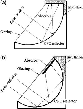
FIGURE 3.7 (a) Inverted flat-plate collector. (b) Inclined flat-plate collector.
A variation of this configuration is the double-sided CPC-type flat-plate collector investigated by Goetzberger et al. (1992) and Tripanagnostopoulos et al. (2000a, b). These are also called bifacial solar flat-plate collectors because the absorber is irradiated at both sides of the absorber. In the design presented by Goetzberger et al. (1992) the absorber is “insulated” in all sides with a transparent insulation whereas in the design presented by Tripanagnostopoulos et al. (2000a, b) a simple glazing was used either in one CPC mirror–absorber unit or in three CPC mirror–absorber units as shown in Figure 3.8(a) and (b), respectively.
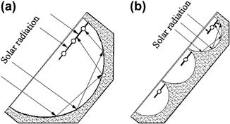
FIGURE 3.8 Cross-section of (a) CPC collector with one mirror–absorber unit and (b) CPC collector with three mirror–absorber units.
3.1.3 Evacuated tube collector (ETC)
Conventional simple flat-plate solar collectors were developed for use in sunny warm climates. Their benefits, however, are greatly reduced when conditions become unfavorable during cold, cloudy, and windy days. Furthermore, weathering influences, such as condensation and moisture, cause early deterioration of internal materials, resulting in reduced performance and system failure. Evacuated heat pipe solar collectors (tubes) operate differently than the other collectors available on the market. These solar collectors consist of a heat pipe inside a vacuum-sealed tube, as shown in Figure 3.9. In an actual installation, many tubes are connected to the same manifold as shown in Figure 3.10.
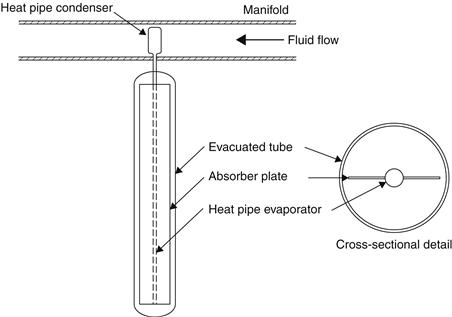
FIGURE 3.9 Schematic diagram of an evacuated tube collector.
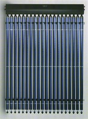
FIGURE 3.10 Actual ETC installation.
Evacuated tube collectors have shown that the combination of a selective surface and an effective convection suppressor can result in good performance at high temperatures. The vacuum envelope reduces convection and conduction losses, so the collectors can operate at higher temperatures than FPCs. Like FPCs, they collect both direct and diffuse radiation, but their efficiency is higher at low incidence angles. This gives ETCs an advantage over FPCs in terms of daylong performance.
ETCs use liquid–vapor phase change materials to transfer heat at high efficiency. These collectors feature a heat pipe (a highly efficient thermal conductor) placed inside a vacuum-sealed tube. The pipe, which is a sealed copper pipe, is then attached to a black copper fin that fills the tube (absorber plate). Protruding from the top of each tube is a metal tip attached to the sealed pipe (condenser). The heat pipe contains a small amount of fluid (e.g. methanol) that undergoes an evaporating–condensing cycle. In this cycle, solar heat evaporates the liquid and the vapor travels to the heat sink region, where it condenses and releases its latent heat. The condensed fluid returns to the solar collector and the process is repeated. When these tubes are mounted, the metal tip projects into a heat exchanger (manifold), as shown in Figure 3.9. Water or glycol flows through the manifold and picks up the heat from the tubes. The heated liquid circulates through another heat exchanger and gives off its heat to a process or water stored in a solar storage tank. Another possibility is to use the ETC connected directly to a hot water storage tank.
Because no evaporation or condensation above the phase change temperature is possible, the heat pipe offers inherent protection from freezing and overheating. This self-limiting temperature control is a unique feature of the evacuated heat pipe collector.
Evacuated tube collectors consist of a heat pipe inside a vacuum-sealed tube. The characteristics of a typical collector are shown in Table 3.2. ETCs on the market exhibit many variations in absorber shape. Evacuated tubes with CPC reflectors are also commercialized by several manufacturers. One such design, presented recently in an attempt to reduce cost and increase lifetime, shown in Figure 3.11, consists of an all-glass Dewar-type ETC. This uses two concentric glass tubes, and the space in between the tubes is evacuated, creating a vacuum jacket. In this type of ETC, the selective coating is deposited onto the outside surface of a glass tube domed at one end. This tube is then inserted into a second, larger diameter domed glass tube and the tubes are joined at the open end. The advantage of this design is that it is made entirely of glass and it is not necessary to penetrate the glass envelope to extract heat from the tube, eliminating leakage losses and keeping it cheaper than the single-envelope system. However, these are suitable only for low-pressure systems and have the disadvantages that the tubes cannot be drained; if one tube breaks, all the working fluid may be lost (Morrison, 2001). This is also called a wet tube ETC. A variation of the wet tube ETC is a normal single-glass ETC in which water (or any other fluid) flows through the collector in either a U tube or a coaxial pipe.
Table 3.2
Characteristics of Typical Evacuated Tube Collector System
| Parameter | Value |
| Glass tube diameter | 65 mm |
| Glass thickness | 1.6 mm |
| Collector length | 1965 mm |
| Absorber plate material | Copper |
| Coating | Selective |
| Absorber area | 0.1 m2 |
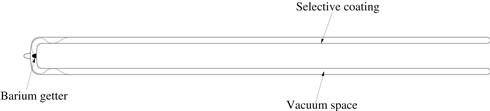
FIGURE 3.11 All-glass Dewar-type evacuated tube collector.
As evacuated tube collectors are relatively expensive, the cost-effectiveness of these collectors can be improved by reducing the number of tubes and using reflectors to concentrate the solar radiation onto the tubes. A diffuse reflector (reflectivity, ρ = 0.6) mounted behind the tubes, spaced one tube diameter apart, as shown in Figure 3.12(a), increases the absorbed energy in each tube by more than 25% for normal incidence. This system also presents a 10% increase in energy collection over a full day because of incidence angle effects. Greater enhancement per tube can be achieved by using CPC-type reflectors, as shown in Figure 3.12(b). Evacuated tube arrays with stationary concentrators may have stagnation temperatures exceeding 300 °C.
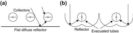
FIGURE 3.12 Evacuated tube collectors array with reflectors. (a) Flat diffuse reflector. (b) CPC reflector.
Another type of collector developed recently is the integrated compound parabolic collector (ICPC). This is an ETC in which, at the bottom part of the glass tube, a reflective material is fixed (Winston et al., 1999). In this case, either a CPC reflector, Figure 3.13(a), or a cylindrical reflector, Figure 3.13(b), is used. The latter does not achieve the concentration of the shaped reflector but has a very low manufacturing cost. In this way, the collector combines into a single unit the advantages of vacuum insulation and non-imaging stationary concentration. In another design, a tracking ICPC is developed that is suitable for high-temperature applications (Grass et al., 2000).
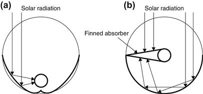
FIGURE 3.13 Integrated CPC tubes. (a) Internal compound parabolic. (b) Circular reflector with finned absorber.
Evacuated tube collectors are produced in a variety of sizes, with outer diameters ranging from 30 to about 100 mm. The usual length of these collectors is about 2 m.
Leave a Reply