As was explained in Chapter 3, Section 3.2.4, power towers or central receiver systems use thousands of individual sun-tracking mirrors, called heliostats, to reflect solar energy onto a receiver located atop a tall tower. The receiver collects the sun’s heat in a heat transfer fluid (molten salt) that flows through the receiver. This is then passed optionally to storage and finally to a power conversion system, which converts the thermal energy into electricity and supplies it to the grid. Therefore, a central receiver system is composed of five main components: heliostats, including their tracking system; receiver; heat transport and exchange; thermal storage; and controls. In many solar power studies, it has been observed that the collector represents the largest cost in the system; therefore, an efficient engine is justified to obtain maximum useful conversion of the collected energy. The power tower plants are quite large, generally 10 MWe or more, while the optimum sizes lie between 50 and 400 MW. It is estimated that power towers could generate electricity at around US$0.04/kWh by 2020 (Taggart, 2008b).
The salt’s heat energy is used to make steam to generate electricity in a conventional steam generator, located at the foot of the tower. The molten salt storage system retains heat efficiently, so it can be stored for hours or even days before being used to generate electricity.
The heliostats reflect solar radiation to the receiver at the desired flux density at minimal cost. A variety of receiver shapes has been considered, including cylindrical receivers and cavity receivers. The optimum shape of the receiver is a function of radiation intercepted and absorbed, thermal losses, cost, and design of the heliostat field. For a large heliostat field, a cylindrical receiver is best suited to be used with Rankine cycle engines. Another possibility is to use Brayton cycle turbines, which require higher temperatures (of about 1000 °C) for their operation; in this case, cavity receivers with larger tower height to heliostat field area ratios are more suitable.
For gas turbine operation, the air to be heated must pass through a pressurized receiver with a solar window. Combined-cycle power plants using this method could require 30% less collector area than the equivalent steam cycles. A first prototype of this system was built within a European research project, and three receiver units were coupled to a 250 kW gas turbine and tested.
Brayton cycle engines provide high engine efficiencies but are limited by the fact that a cavity receiver is required, which reduces the numbers of heliostats that can be used. Rankine cycle engines, driven from steam generated in the receiver and operated at 500–550 °C, have two important advantages over the Brayton cycle. The first is that the heat transfer coefficients in the steam generator are high, allowing the use of high-energy densities and smaller receivers. The second is that they employ cylindrical receivers, which permit larger heliostat fields to be used.
The U.S. Department of Energy and a consortium of U.S. utilities and industry built the first large-scale, demonstration solar power tower, called the Solar One, in the desert near Barstow, California. The plant operated successfully from 1982 to 1988, and the main outcome of the project was to prove that power towers could work efficiently to produce utility-scale power from sunlight. The system had the capacity to produce 10 MW of power. This plant used water-steam as the heat transfer fluid in the receiver, which presented several problems in terms of storage and continuous turbine operation.
These problems were addressed by Solar Two, which was an upgrade of Solar One. Solar Two operated from 1996 to 1999. Solar Two demonstrated how solar energy can be stored efficiently and economically as heat in tanks of molten salt, so that power can be produced even when the sun is not shining. The Solar Two plant used nitrate salt (molten salt, 60% NaNO3 + 40% KNO3) as both the heat transfer fluid in the receiver and the heat storage media. In this plant, the molten nitrate salt at 290 °C was pumped from a cold storage tank through the receiver, where it was heated to approximately 565 °C and then traveled to a storage tank, which had a capacity of 3 h of storage. A schematic of the system is shown in Figure 10.5.
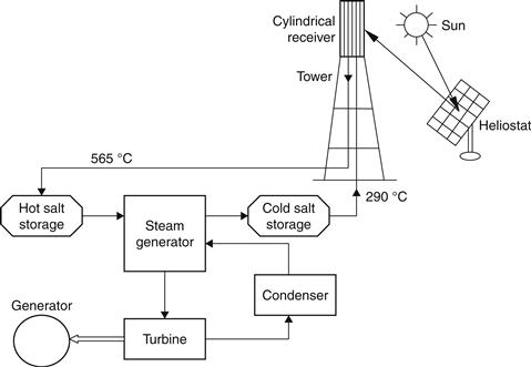
FIGURE 10.5 Schematic of the Solar Two plant.
When power is needed from the plant, the hot salt is pumped to a generator that produces steam. The steam activates a turbine-generator system that creates electricity. From the steam generator, the salt is returned to the cold storage tank, where it is stored and can be eventually reheated in the receiver.
By using thermal storage, power tower plants can potentially operate for 65% of the year with no need for a backup fuel source. Without energy storage, solar technologies such as the parabolic trough plants are limited to annual capacity factors near 25%.
A commercial 10 MW solar tower, called PS10 and a 20 MW system called PS20 are currently operating near Seville, Spain. The plants are located 20 km west of Seville, which receives at least 9 h of sunshine 320 days per year, with 15 h per day in mid-summer. Each of the 624 heliostats of PS10 has a surface area of 120 m2 that concentrates the sun’s rays to the top of a 115 m high tower where a solar receiver and a steam turbine are located. The solar receiver produces saturated steam at 275 °C. The energy conversion efficiency is approximately 17%. PS20 consists of a solar field of 1255 heliostats designed by Abengoa Solar. Each heliostat with a surface area of 120 m2 (same as PS10) reflects the solar radiation onto the receiver, located on the top of a 165 m high tower, producing steam which is converted into electricity by a turbine generator.
Another plant operated recently is Gemasolar. This power plant, which is also near Seville, is the first commercial solar thermal power plant to supply uninterrupted power for a full 24 h. Owned by Torresol Energy, Gemasolar, originally named Solar Tres, is the first commercial plant in the world to use molten salt thermal storage in a central tower configuration with a heliostat field (see Figure 10.6). Gemasolar is seen as a breakthrough in the CSP sector, and its commercial operation is expected to lead the way for other central tower plants with molten salt receiver technology, an efficient system that improves the dispatchability of electric power from renewable sources.
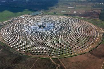
FIGURE 10.6 Gemasolar power system located near Seville, Spain. Image by Torresol Energy.
The Gemasolar Concentrated Solar Power system has a capacity of 19.9 MW and consists of an array of 2650 heliostats that aim solar radiation at the top of a 140 m height central tower. The radiation heats molten salt that circulates inside the receiver to temperatures of more than 500 °C. The hot molten salt is then stored in tanks that are specially designed to maintain the high temperatures. These high temperatures in turn generate hotter, with respect to other CSP systems, pressurized steam, which significantly increases the plant’s efficiency. The heat storage system enables the power plant to run steam turbines and generate electricity for up to 15 h without any incoming solar radiation. Therefore, the salt storage capacity enables the plant to supply energy to the grid based on demand, regardless of whether there is solar radiation.
Gemasolar’s ability to generate 24 h of electricity marks an important step toward demonstrating the reliability of solar technology, which is one of the industry’s biggest challenges. In addition to providing continuous power on cloudy days and at night, Gemasolar’s storage capacity makes it possible to manage the supply of electricity sent to the network, and to respond to sudden increases in demand. In this way, the reliability of solar energy becomes comparable to that of conventional fossil-fueled power plants, which is important for the future adoption of renewable energy systems.
The power generated by Gemasolar is supplied to a nearby power substation, where it is fed into the grid. Gemasolar can supply electricity to about 27,500 households in the South of Spain, as well as reduce carbon dioxide emissions by more than 30,000 tons per year. The plant is expected to produce a net total of over 110 GWh per year, by operating for a total of 6450 h a year at full capacity.
Another important system is the construction of an experimental 1.5 MWe solar tower power plant in Germany. It has been operational since December 2008 and started the production of electricity in spring 2009. The plant, shown in Figure 10.7, was built by Kraftanlagen München and is operated by the local utility Stadtwerke Jülich. The location of Jülich was chosen because of its fluctuating direct solar radiation, which allows, and requires, investigation of the system operation strategy under transient conditions—especially in combination with thermal storage. The objective of the solar power tower project in Jülich is to demonstrate the entire system.
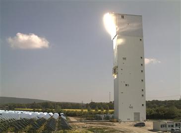
FIGURE 10.7 Solar tower Jülich.
The concentrator system consists of 2150 sun-tracking heliostats of about 8 m2 reflective surface each and reflects the sunlight onto a 22 m2 receiver aperture that has the shape of an inclined segment of a cylinder. The open volumetric receiver technology applied is used to heat up ambient air to high temperatures for steam generation in a boiler of a conventional steam turbine cycle. The porous absorber located at the top of a 60 m tower collects the highly concentrated solar radiation inside a honeycomb structure allowing the heat to be transferred to the air very effectively.
The advantages of this technology are simplicity and scalability, the ability to include a thermal storage, the low thermal capacity (quick start-up), and a high efficiency potential due to high achievable temperatures. A thermal storage unit is integrated into the air cycle, through which the operation of the power plant can be held for a certain time at constant power, depending on the storage dimensions. Generally, this thermal storage can be designed with an unlimited capacity, securing a continuous power plant operation. It is used as a buffer, storing energy in times of high irradiation, and enables operation of the plant after sunset or during periods of cloudy weather.
10.3.1 System characteristics
Central receiver (or power tower) systems use a field of distributed mirrors, called heliostats, that individually track the sun and focus the sunlight on the top of a tower. By concentrating the sunlight 300–1500 times, they can achieve temperatures from 800 to over 1000 °C. The solar energy is absorbed by a working fluid, which is subsequently used to generate steam to power a conventional turbine. The average solar flux impinging on the receiver has values between 200 and 1000 kW/m2. This high flux allows working at relatively high temperatures and integrating solar thermal energy in more efficient cycles.
Central receiver systems can easily be hybridized in a wide variety of options and have the potential to operate more than half the hours of each year at nominal power using a thermal energy storage. The central receiver plant is characterized by the heat transfer fluid, thermal storage medium, and power conversion cycle used. The heat transfer fluid may either be water-steam, liquid sodium, or molten nitrate salt (sodium nitrate–potassium nitrate), whereas the thermal storage medium may be oil mixed with crushed rock, molten nitrate salt, or liquid sodium.
In the initial central receiver plants, a receiver made from bundles of steel tubes on top of the tower was used to absorb the concentrated solar heat coming from the heliostat field. The Solar Two plant in California used molten salt as the heat transfer fluid and the thermal storage medium for nighttime operation. In Europe, air is preferred as the heat transfer medium, but tube receivers are not appropriate for this purpose because of a poor heat transfer and local overheating of the tubes. Therefore, within the PHOEBUS project in the 1990s, a volumetric receiver was developed using a wire mesh directly exposed to the incident radiation and cooled by air flowing through that mesh. In this project, the receiver achieved 800 °C and was used to operate a 1 MW steam cycle. A ceramic thermal heat storage was used for nighttime operation. A larger plant of 2.5 MW (thermal), based on this concept, was tested at the Plataforma Solar in the Almeria research center. In this plant, the solar energy is collected by 350 heliostats, each 40 m2 in area. For even higher temperatures, the wire mesh screens are replaced by porous SiC or Al2O3 structures.
A European industry group, the PHOEBUS consortium, is leading the way with air-based systems. Air heat transfer receivers allow operation at significantly higher outlet temperatures, require higher operating pressures, but have relatively high heat losses compared to water-steam receivers. For these reasons, the PHOEBUS consortium developed a novel technology solar air (TSA) receiver, which is a volumetric air receiver that distributes the heat-exchanging surface over a three-dimensional volume and operates at ambient pressures. The greatest advantages of this system are its relative simplicity and safety. These make it ideal for applications in developing countries.
A photograph of the Solar Two system is shown in Figure 10.8. The heliostat system consists of 1818 individually oriented reflectors made of back-silvered glass, each consisting of 12 concave panels with a total area of 39.13 m2 (see Figure 10.9), for a total mirror area of 71,100 m2. The receiver of the plant is a single-pass superheated boiler, which is cylindrical in shape, 13.7 m in height, and 7 m in diameter. It is an assembly of 24 elements, each 0.9 m wide and 13.7 m long. Six of the elements on the south side, which receives the least radiation, are used as feed-water preheaters, and the rest are used as boilers. The top of the tower is 90 m above the ground. The receiver was designed to produce 50,900 kg/h of steam at 565 °C with the absorber operating at 620 °C. A detail of the receiver of Solar Two is also shown in Figure 10.9.
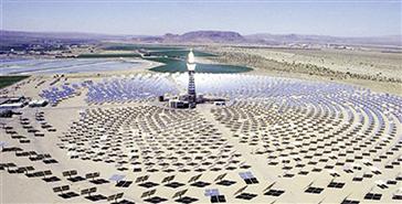
FIGURE 10.8 Photograph of the Solar Two central receiver plant. http://www.sandia.gov/
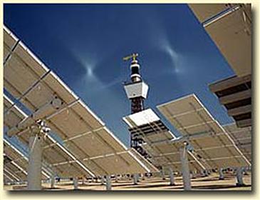
FIGURE 10.9 Heliostat detail of the Solar Two plant. http://www.sandia.gov/
The general requirements to install a solar tower plant are a site with high direct normal insolation, and the site needs to be level and have available water for the cooling towers.
Leave a Reply