
Photovoltaic modules can be mounted on the ground or a building roof or can be included as part of the building structure, usually the façade. Wind and snow loading are major design considerations. The PV modules can last more than 25 years, in which case the support structures and building should be designed for at least as long as the same lifetime. Related equipment includes batteries, charge controllers, inverters, and peak-power trackers.
9.3.1 Batteries
Batteries are required in many PV systems to supply power at night or when the PV system cannot meet the demand. The selection of battery type and size depends mainly on the load and availability requirements. When batteries are used, they must be located in an area without extreme temperatures, and the space where the batteries are located must be adequately ventilated.
The main types of batteries available today include lead-acid, nickel cadmium, nickel hydride, and lithium. Deep-cycle lead-acid batteries are the most commonly used. These can be flooded or valve-regulated batteries and are commercially available in a variety of sizes. Flooded (or wet) batteries require greater maintenance but, with proper care, can last longer, whereas valve-regulated batteries require less maintenance.
The principal requirement of batteries for a PV system is that they must be able to accept repeated deep charging and discharging without damage. Although PV batteries have an appearance similar to car batteries, the latter are not designed for repeated deep discharges and should not be used. For more capacity, batteries can be arranged in parallel.
Batteries are used mainly in stand-alone PV systems to store the electrical energy produced during the hours when the PV system covers the load completely and there is excess or when there is sunshine but no load is required. During the night or during periods of low solar irradiation, the battery can supply the energy to the load. Additionally, batteries are required in such a system because of the fluctuating nature of the PV system output.
Batteries are classified by their nominal capacity (qmax), which is the number of ampere hours (Ah) that can be maximally extracted from the battery under predetermined discharge conditions. The efficiency of a battery is the ratio of the charge extracted (Ah) during discharge divided by the amount of charge (Ah) needed to restore the initial state of charge (SOC). Therefore, the efficiency depends on the SOC and the charging and discharging current. The SOC is the ratio between the present capacity of the battery and the nominal capacity; that is,
![]() (9.22)
(9.22)
As can be understood from the preceding definition and Eq. (9.22), SOC can take values between 0 and 1. If SOC = 1, then the battery is fully charged; and if SOC = 0, then the battery is totally discharged.
Other parameters related to batteries are the charge or discharge regime and the lifetime of the battery. The charge (or discharge) regime, expressed in hours, is the parameter that reflects the relationship between the nominal capacity of a battery and the current at which it is charged (or discharged)—for example, a discharge regime is 40 h for a battery with nominal capacity of 200 Ah that is discharged at 5 A. The lifetime of the battery is the number of charge–discharge cycles the battery can sustain before losing 20% of its nominal capacity.
In general, the battery can be viewed as a voltage source, E, in series with an internal resistance, Ro, as shown in Figure 9.13. In this case, the terminal voltage, V, is given by:
![]() (9.23)
(9.23)
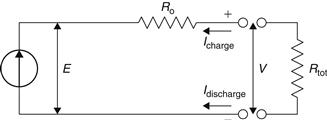
FIGURE 9.13 Schematic diagram of a battery.
9.3.2 Inverters
An inverter is used to convert the direct current into alternating current electricity. The output of the inverter can be single or three phase. Inverters are rated by the total power capacity, which ranges from hundreds of watts to megawatts. Some inverters have good surge capacity for starting motors, and others have limited surge capacity. The designer should specify both the type and size of the load the inverter is intended to service.
The inverter is characterized by a power-dependent efficiency, ηinv. Besides changing the DC into AC, the main function of the inverter is to keep a constant voltage on the AC side and convert the input power, Pin, into the output power, Pout, with the highest possible efficiency, given by:
![]() (9.24)
(9.24)
Idc = current required by the inverter from the DC side, i.e., controller (A); and
Vdc = input voltage for the inverter from the DC side, i.e., controller (V).
Numerous types of inverters are available, but not all are suitable for use when feeding power back into the mains supply.
The efficiency of an inverter depends on the fraction of its rated power at which it operates. A PV system operates at high efficiency either when it has one inverter operating with a load large enough to maintain peak efficiency or is an interconnection of module-integrated inverters or master-slave configurations (Woyte et al., 2000). When one inverter is used, this is supplied with power from several series-connected PV modules connected in parallel on a DC bus. This configuration has a low-cost and provides high efficiency but requires a complex DC installation. In a module-integrated inverter, each PV module has its own individual inverter, called micro-inverter (see Section 9.3.4). These are more expensive than a central inverter; however, they prevent the use of expensive DC wiring (Woyte et al., 2000). A master-slave configuration requires multiple inverters connected together and generally can give greater PV output. At low solar irradiation, all the PVs of the array are connected to just a single inverter operating the inverter at its peak input power level, when solar irradiation increases the PV array is divided progressively into smaller sets of PVs, until every inverter operates independently at or near its peak rated capacity. Module-integrated inverters are located generally at the back of each module converting its DC output to AC power.
Inverter efficiency reaches its maximum, above 90%, for an input power level usually between 30% and 50% of its rated capacity. When a PV module is shaded, the PV output current decreases significantly, causing not only the particular module output power to drop, but the output power also drops which in turn affects inverter performance (Hashimoto et al., 2000).
The performance of an inverter depends on its point of work, threshold of operation, inverter output waveform, harmonic distortion and frequency, PV efficiency, maximum power point tracker (MPPT) and transformer (Norton et al., 2011). The main functions of an inverter are wave-shaping, regulation of output voltage, and operation near peak power point (Kjar et al., 2005). The three major types of inverter are sine wave, modified sine wave, and square wave. The major advantage of a sine wave inverter is that most appliances are designed for a sine-wave operation. A modified sine-wave inverter has a waveform more like a square wave, but with an extra step, can also operate with most appliances. Finally, a square-wave inverter can generally operate only simple devices with universal motors but its greatest advantage is that it is much cheaper than the sine-wave inverter. Additionally, using a power filter, the output square waveform can be converted to a sine waveform.
9.3.3 Charge controllers
Controllers regulate the power from PV modules to prevent the batteries from overcharging. The controller can be a shunt type or series type and also function as a low-battery voltage disconnect to prevent the battery from over-discharge. The controller is chosen for the correct capacity and desired features (ASHRAE, 2004).
Normally, controllers allow the battery voltage to determine the operating voltage of a PV system. However, the battery voltage may not be the optimum PV operating voltage. Some controllers can optimize the operating voltage of the PV modules independently of the battery voltage so that the PV operates at its maximum power point.
Any power system includes a controller and a control strategy, which describes the interactions between its components. In PV systems, the use of batteries as a storage medium implies the use of a charge controller. This is used to manage the flow of energy from PV system to batteries and load by using the battery voltage and its acceptable maximum and minimum values. Most controllers have two main modes of operation:
1. Normal operating condition, where the battery voltage varies between the acceptable maximum and minimum values.
2. Over-charge or over-discharge condition, which occurs when the battery voltage reaches a critical value.
The second mode of operation is obtained by using a switch with a hysteresis cycle, such as electromechanical or solid-state devices. The operation of this switch is shown in Figure 9.14.
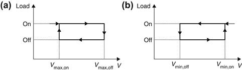
FIGURE 9.14 Operating principle of over-charge and over-discharge protection. (a) Over-charge. (b) Over-discharge.
As shown in Figure 9.14(a), when the terminal voltage increases above a certain threshold, Vmax,off, and when the current required by the load is less than the current supplied by the PV array, the batteries are protected from excessive charge by disconnecting the PV array. The PV array is connected again when the terminal voltage decreases below a certain value, Vmax,on (Hansen et al., 2000).
Similarly, as shown in Figure 9.14(b), when the current required by the load is bigger than the current delivered by the PV array, to protect the battery against excessive discharge the load is disconnected when the terminal voltage falls below a certain threshold, Vmin,off. The load is connected to the system again when the terminal voltage is above a certain threshold, Vmin,on (Hansen et al., 2000).
9.3.4 Peak-power trackers
As was seen before, PV cells have a single operating point where the values of the current (I) and voltage (V) of the cell result in a maximum power output. These values correspond to a particular resistance, which is equal to V/I, as specified by Ohm’s law. A PV cell has an exponential relationship between current and voltage, and there is only one optimum operating point, also called a maximum power point (MPP), on the power–voltage (or current) curve, as shown in Figure 9.8. MPP changes according to the radiation intensity and the cell temperature, as shown in Figure 9.9. Maximum power point trackers (MPPTs) utilize some type of control circuit or logic to search for this point and, thus, allow the converter circuit to extract the maximum power available from a cell. In fact, peak-power trackers optimize the operating voltage of a PV system to maximize the current. Typically, the PV system voltage is charged automatically. Simple peak-power trackers may have fixed operator-selected set points.
MPP trackers can either be applied at the array level or at the module level. In the former, a single tracker controls the current through all modules in the array. This function in fact is commonly integrated into the array’s inverter, as already indicated in Section 9.3.2. The advantage of this approach is that a single large inverter/controller is used, which simplifies maintenance, minimizes cost, and allows high inverter efficiency. Its drawback is that the same current flows through all modules that are connected in series in the array, and because some modules may have different I–V curves than others, not all modules will operate at their individual maximum power point. This is especially problematic when inconsistent manufacturing leads to variability between modules—“module mismatch”—and when modules in an array experience different amounts of shading or soiling. Modules may also age at different rates, causing further variation in I–V curves.
To overcome this problem, MPP controllers can be applied to individual modules in an array, so that every module operates at its own maximum power point. These may either be DC–DC controllers, which still require a central inverter, or DC–AC “micro-inverters” which perform both MPP control and inversion as is seen also in Section 9.3.2. Manufacturers of both devices claim that they can increase the yield of a PV array by 5–20%. In addition, they allow malfunctioning modules in a system to be more easily identified, as the output of each module is monitored. However multiple small controllers inherently cost more than a single centralized one. Therefore, a cost/benefit analysis needs to be carried out before choosing the right system to make sure that the extra energy collected offsets the extra cost of the MPP.
Micro-inverters have additional advantages: AC power is simpler to connect to a building’s electrical system, they operate at safer voltages than central inverters (200–300 V, as opposed to 600 or 1000 V), and inverter failure means the loss of only a single module, not an entire array. However micro-inverters are not yet as reliable as large inverters, especially at high temperatures.
With these characteristics, MPP of individual modules is most suited to PV systems subject to shading or infrequent cleaning, and where the value of produced electricity is high. DC–DC and DC–AC module controllers are widely available in the market, and some modules now have DC–DC controllers built into them. They are used in both residential and commercial PV systems.
In PV systems designed to charge batteries for off-grid power systems, MPPT charge controllers are desirable to make the best use of all the energy generated by the panels. MPPT charge controllers are quickly becoming more affordable and more common. The benefits of MPPT regulators are greatest during cold weather, on cloudy or hazy days, or when the battery is deeply discharged. Peak-power trackers can be purchased separately or specified as an option with battery charge controllers or inverters. In all cases, however, the cost and complexity of adding a peak-power tracker should be balanced against the expected power gain and the impact on system reliability.
Leave a Reply