Author: workhouse123
-

Introduction
The term automation is used to describe the automatic operation or control of a process. In modem manufacturing there is an ever increasing use of automation, e.g., automatically operating machinery, perhaps in a production line with robots, which can be used to produce components with virtually no human intervention. Also, in appliances around the home and in…
-
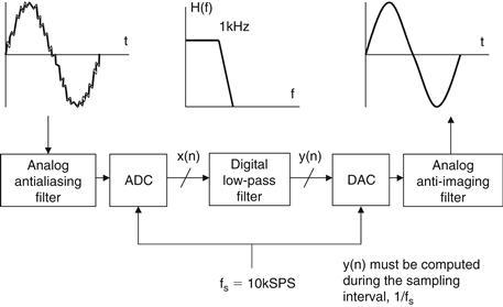
A Practical Example
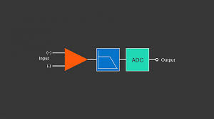
As a practical example of the power of DSP, consider the comparison between an analog and a digital low-pass filter, each with a cutoff frequency of 1 kHz. The digital filter is implemented in a typical sampled data system shown in Figure 16.4. Note that there are several implicit requirements in the diagram. First, it is assumed that…
-
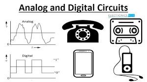
Analog Versus Digital Signal Processing
Today’s engineer faces a challenge in selecting the proper mix of analog and digital techniques to solve the signal processing task at hand. It is impossible to process real-world analog signals using purely digital techniques, since all sensors, including microphones, thermocouples, strain gages, piezoelectric crystals, and disk drive heads are analog sensors. Therefore, some sort…
-
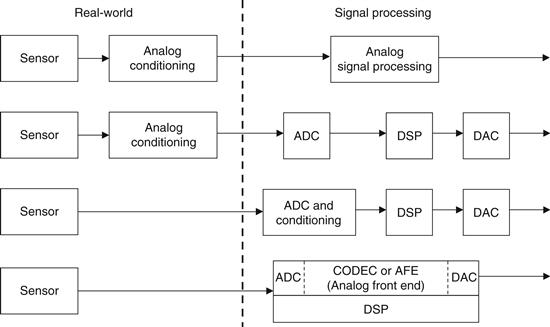
Methods and Technologies Available for Processing Real-World Signals
Signals may be processed using analog techniques (analog signal processing, or ASP), digital techniques (digital signal processing, or DSP), or a combination of analog and digital techniques (mixed-signal processing, or MSP). In some cases, the choice of techniques is clear; in others, there is no clear-cut choice, and second-order considerations may be used to make…
-
Generation of Real-World Signals
In most of the previous examples (the ones requiring DSP techniques), both ADCs and DACs are required. In some cases, however, only DACs are required where real-world analog signals may be generated directly using DSP and DACs. Video raster scan display systems are a good example. The digitally generated signal drives a video or RAMDAC.…
-
Reasons for Processing Real-World Signals
The primary reason for processing real-world signals is to extract information from them. This information normally exists in the form of signal amplitude (absolute or relative), frequency or spectral content, phase, or timing relationships with respect to other signals. Once the desired information is extracted from the signal, it may be used in a number…
-
Origins of Real-World Signals and their Units of Measurement
In this chapter, we will primarily be dealing with the processing of real-world signals using both analog and digital techniques. Before starting, however, let’s look at a few key concepts and definitions required to lay the groundwork for things to come (Figure 16.1). Figure 16.1 Signal characteristics Webster’s New Collegiate Dictionary defines a signal as “a…
-
Current Division
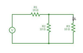
For the circuit shown in Figure 3.18, the total circuit resistance RT is given by: Figure 3.18 : Current division circuit and Current Similarly, current Summarizing, with reference to Figure 3.18: Example 3.11 For the series-parallel arrangement shown in Figure 3.19, find (a) the supply current, (b) the current flowing through each resistor and (c) the voltage across each resistor. Figure…
-
Parallel Networks
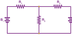
shows three resistors, R1, R2 and R3 connected across each other, i.e., in parallel, across a battery source of V volts. Figure 3.9 : Parallel resistors In a parallel circuit: (a) the sum of the currents I1, I2 and I3 is equal to the total circuit current, I, i.e., I =I1 +I2 +I3, and (b) the source voltage, V volts, is the same across each of the resistors. From Ohm’s law: where R is the total circuit resistance. Since I =I1 +I2 +I3…
-
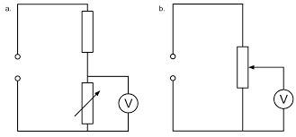
Potential Divider
The voltage distribution for the circuit shown in Figure 3.5(a) is given by: Figure 3.5 : Potential divider circuit The circuit shown in Figure 3.5(b) is often referred to as a potential divider circuit. Such a circuit can consist of a number of similar elements in series connected across a voltage source, voltages being taken from connections between the elements. Frequently the…