Author: workhouse123
-

Power Factor Is Unity (cos ɸ = 1) or ɸ = 0°
For pure resistance load, the power factor is unity, that is,cos ɸ= 1 or ɸ= 0°. Then, two wattmeter readings will be W1 = VL ILcos (30° − 0) = VL ILcos 30° W2 = VL ILcos (30° + 0) = VL ILcos 30°, i.e., W1 = W2 Hence, when power factor is unity, both the wattmeters give equal reading. 8.17.2 Power Factor Is 0.5 (cosɸ= 0.5) or ɸ= 60° Under such conditions,…
-
TWO-WATTMETER METHOD (BALANCED LOAD)
The two-wattmeter method can be explained somewhat more clearly by considering a balanced load. In this case, we shall prove that power measured by the two wattmeters (i.e.,sum of two wattmeter readings) is equal to VLIL cosɸ, which is the actual power consumed in a three- phase balanced load. The connection diagram for a three-phase balanced load…
-
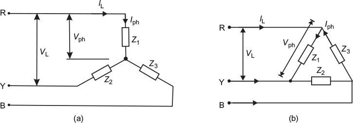
CONNECTIONS OF THREE-PHASE LOADS
Similar to three-phase supply, the three-phase loads may also be connected in star or delta. The three-phase loads connected in star and delta are shown in Figure 8.8(a) and (b), respectively. The three-phase loads may be balanced or unbalanced. If the three loads (impedances) Z1, Z2, and Z3 are having same magnitude and phase angle, then the three-phase load is said to be…
-
MESH OR DELTA (∆) CONNECTION
In delta (∆) or mesh connections, the finish terminal of one winding is connected to start terminal of the other winding and so on, which forms a closed circuit. The three line conductors are run from three junctions of the mesh called line conductors, as shown in Figure 8.6. Fig. 8.6 (a) Three phases connected in delta…
-
STAR OR WYE (Y) CONNECTION
In star or wye (Y) connections, the similar ends (either start or finish) of the three windings are connected to a common point called star or neutral point. The three line conductors are run from the remaining three free terminals called line conductors. Ordinarily, only three wires are carried to the external circuit giving three-phase,…
-
INTERCONNECTION OF THREE PHASES
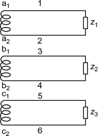
In a three-phase AC generator, three are three windings. Each winding has two terminals (start and finish). If a separate load is connected across each phase winding as shown in Figure 8.3, then each phase supplies an independent load through a pair of leads (wires). Thus, six wires will be required in this case to connect…
-
DOUBLE-SUBSCRIPT NOTATION
An alternating quantity is generally represented by a double-subscript notation. In this notation, two letters are placed at the foot of the symbol for voltage or current, as shown in Figure 8.2. This conveys the following two scenarios: Fig. 8.2 Circuit to represent double subscript notation For instant, the current is represented as Iab. It means that The double-subscript…
-
PHASE SEQUENCE
In a three-phase system, there are three voltages having same magnitude and frequency displaced by an angle of 120° electrical. They are attaining their positive maximum value in a particular order. The order in which the voltages (or emfs) in the three phases attain their maximum positive value is called the phase sequence. The emfs…
-
NAMING THE PHASES
The three phases may be represented by numbers (1, 2, and 3) or by letters (a, b, and c) or by colours (red, yellow, and blue,i.e.,R, Y, and B). In India, they are named by R, Y, and B,that is, red, yellow, and blue.
-
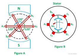
GENERATION OF THREE-PHASE EMFS
In a three-phase system, there are three equal voltages (or emfs) of the same frequency having a phase difference of 120°. These voltages can be produced by a three-phase, AC generator having three identical windings (or phases) displaced 120° electrical apart. When these windings are rotated in a stationary magnitude field (see Fig. 8.1(a)) or…