Author: workhouse123
-
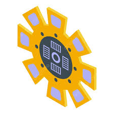
SINGLE PLATE CLUTCH
In a single plate clutch, a flywheel ‘A’ is bolted to a flange on the driving shaft B. The friction plate C is fixed to a hub which can slide on the spline, i.e., driven shaft ‘D’. Two rings of friction material are riveted to flange ‘A’ and the plate ‘C’. The pressure plate ‘E’…
-
INTRODUCTION TO CLUTCHES
Clutch is a device which is used to engage and disengage the driven shaft from driving shaft during the motion to change the gears meshing without stopping the driving shaft. Its operation is based on the friction between two surfaces; friction torque is applied by driving shaft on driven shaft. Clutch may be classified as…
-
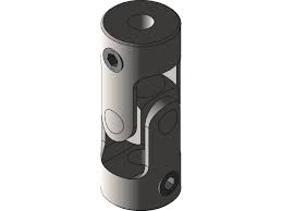
UNIVERSAL JOINT
To accommodate misalignment between mating shafts for more than the 3°, a universal joint is used. Angular misalignments of up to 45° are possible at low rotational speeds with single universal joints. It consists of two yokes, a centre bearing block, and two pins that pass through the block at right angles. Approximately 20° –…
-
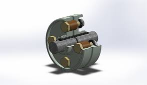
FLEXIBLE BUSHED COUPLING
In a rigid coupling, the torque is transmitted from one half of the coupling to the other through the bolts and in this arrangement shafts need be aligned very well. However, in the bushed coupling the rubber bushings over the pins (bolts) (as shown in Figure 16.2) provide, flexibility and can accommodate, some misalignment. Because of…
-
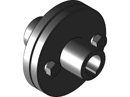
RIGID COUPLING
Rigid couplings are designed to draw two shafts together tightly so that no relative motion can occur between them. This design is used for some special kinds of equipment in which precise alignment of two shafts is required. In such cases, the coupling must be capable of transmitting the torque in the shafts. Rigid couplings…
-

INTRODUCTION TO COUPLING
The term coupling is a device used to connect two shafts together at their ends for transmitting the power. There are a number of coupling devices used to couple two shafts but in this chapter only few important couplings have been introduced for understanding of the students. There are two general types of couplings:
-

TEMPERATURE STRESS
If the temperature of a material is increased, there will be expansion in the material (except ice) and if the temperature is decreased, there will be contraction in the material. If these expansion and contraction occur freely there will be no stress in the material and if these expansion or contraction is prevented then stress…
-

STRESS AND STRAIN IN COMPOSITE BAR
Any tensile or compressive member which consists of two or more bars in series, usually of different materials, is called composite bars (Figure 12.18). In this case, load on both the rods will be same but strain produced will be different. Figure 12.18 Composite Bar where A1, E1 ∈1 are cross-section area, modulus of elasticity, and strain produced in material…
-

STRESS AND STRAIN IN VARYING CROSS-SECTION BAR OF UNIFORM STRENGTH
Consider a bar of varying cross-section of uniform strength subjected by a longitudinal stress σ as shown in Figure 12.10. Now consider a small element of axial length δx at a distance of x from smaller end. Let area of cross-section at section x be A and at section x + δx be A +…
-
EXTENSION IN VARYING CROSS-SECTION OR TAPER ROD
A rod of length l tapers uniformly from a diameter D at one end to diameter d at other end as shown in Figure 12.8. Considering an small element of thickness dx at distance x from the end of diameter d, the diameter of the element is calculated as Figure 12.8 Extension in Taper Rod Example 12.4: A rod tapers uniformly from 50 to 20 mm diameter in a length…