Category: 5. Magnetic Circuits
-

INDUCTANCES IN SERIES AND PARALLEL
Consider two coils magnetically coupled having self-inductance of L1 and L2, respectively, and a mutual inductance of M H. The two coils, in an electrical circuit, may be connected in different ways giving different values of resultant inductance as the following. 5.23.1 Inductances in Series The two coils may be connected in series in two ways: when their fields (or mmfs)…
-

CO-EFFICIENT OF COUPLING
When current flows through one coil, it produces flux (f1). The whole of this flux may not be linking with the other coil coupled to it, as shown in Figure 5.32. It may be reduced because of leakage flux fl by a fraction k known as co-efficient of coupling. Fig. 5.32 Magnetic circuit for co-efficient of coupling Thus, the fraction…
-
SELF-INDUCTANCE
The property of a coil due to which it opposes the change of current flowing through itself is called self-inductance or inductance of the coil. This property (i.e., inductance) is attained by a coil due to self-induced emf produced in the coil itself by the changing current flowing through it. If the current in the coil is…
-
statically induced emf
When both the coil and magnetic field system are stationary but the magnetic field linking with the coil changes (by changing the current producing the field), the emf thus induced in the coil is called statically induced emf. The statically induced emf are of two types: self-induced emf and mutually induced emf. 5.19.1 Self-induced Emf The emf induced…
-
DYNAMICALLY INDUCED EMF
By either moving the conductor and keeping the magnetic field system stationary, or moving the field system and keeping the conductor stationary so that flux is cut by the conductor, the emf thus induced in the conductor is called dynamically induced emf. 5.18.1 Mathematical Expression Considering a conductor of length l m placed in the magnetic field of flux…
-
DIRECTION OF INDUCED EMF
The direction of induced emf and hence current in a conductor or coil can be determined by either of the following two methods: When N-pole of a bar magnet is taken near to the coil, as shown in Figure 5.28 (a), an emf is induced in the coil, and hence, current flows through it in such a…
-
FARADAY’S LAWS OF ELECTROMAGNETIC INDUCTION
Michael Faraday summed up conclusions of his experiments regarding electromagnetic induction into two laws, known as Faraday’s laws of electromagnetic induction. 5.15.1 First Law This law states that ‘Whenever a conductor cuts across the magnetic field, an emf is induced in the conductor’. or ‘Whenever the magnetic flux linking with any circuit (or coil) changes, an emf…
-
Residual Magnetism and Retentivity
This value of flux density ‘ob’ retained by the magnetic material is called residual magnetism and the power of retaining this residual magnetism is called retentivity of the material. To demagnetise the magnetic ring, the magnetising force H is reversed by reversing the direction of flow of current in the solenoid. This is achieved by changing the…
-
MAGNETISATION OR B−H CURVE
The graph plotted between flux density B and magnetising force H of a material is called the magnetisationor B−H curveof that material. The general shape of the B−H curve of a magnetic material is shown in Figure 5.20. The shape of the curve is non-linear. This indicates that the relative permeability (µr =B/µ0H) of a magnetic material is not constant but it varies. The value of μr largely…
-
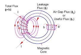
LEAKAGE FLUX
The magnetic flux that does not follow the intended path in a magnetic circuit is called leakage flux. Fig. 5.7 Magnetic circuit with leakage flux When some current is passed through a solenoid, as shown in Figure 5.7, magnetic flux is produced by it. Most of this flux is set up in the magnetic core and passes…