Category: Filter Design
-
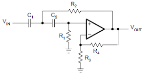
Second-Order High-Pass Filters
High-pass filters may be designed in a similar manner to low-pass second-order filters, but in this case the normalized response is slightly different. The response for such a filter may be given as: (17.18) As before two cases are deduced: the Chebyshev response, where an the Butterworth response, where . These responses are shown in Figure 17.18. Figure…
-

Using Identical Components
It is simpler sometimes to use equal components, but it is necessary to adhere to the particular pass-band gain on the normalized tables. In many applications this method should be considered first. Select a cut-off frequency value and then choose a common value for C=C1=C2—some value less than 1 mF, say. Since R=R1=R2, R can now be calculated as follows:…
-
Using Normalized Tables
If normalized tables are available these can be easily used without much calculation. A set of these tables is shown in Table 17.2. As can be seen, if the pass-band gain (K) is known it is simply a matter of selecting the appropriate values. Note that several combinations may be possible, as was the case with…
-
Using the Transfer Function
Determine suitable values for R1, R2, C1 and C2 for a second-order Butterworth filter with an upper cut-off frequency of 4 kHz and a pass-band gain of 20. Solution A problem of this nature requires a normalized response before it can be solved. The second-order Butterworth normalized response in this case will be given as: (17.9) and the transfer function will be…
-
Second-Order Filters
As has already been mentioned, the higher the order of filter the sharper the cut-off. For certain applications, such as radio relay applications and channel separation, it is necessary to have higher-order filters. This chapter only looks at first and second-order filters but many higher orders can be designed by simply cascading these two types;…
-
Design of First-Order Filters
Low- and high-pass first-order filters may be designed very easily if certain steps are followed: 1. The cut-off frequency must be known. 2. A value of C less than 1 μF (say) should be chosen. 3. Then calculate the value of R from equation (17.4) or (17.6), depending on the filter being designed. 4. Determine a value of A and calculate Rf and R1. Example 17.1…
-
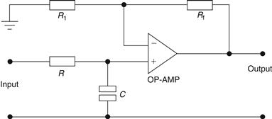
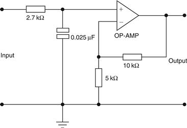
First-Order Filters
The first-order filter is the simplest type and forms the basis of all other filters. Normally, what is called the Butterworth type is analyzed. We will look at the low-pass filter first, a circuit for which is shown in Figure 17.9. Figure 17.9 Low-pass Butterworth filter In this circuit note that the op-amp is ideal, i.e., it draws no…
-
Active Filters
The use of operational amplifiers in active filter devices is now well established in communications systems. Their main advantages over passive filters are: (a) flexibility in design and construction; (b) the absence of inductors, which at low frequencies is useful due to their large size and cost; (c) low-frequency applications down to 1 Hz; (d) the buffering effect due to…
-
Passive Filters
The most elementary types of filters are constructed from RC networks and are known as passive filters as they dissipate part of the signal power and pass the rest. Figure 17.3(a) shows a passive low-pass filter, while Figure 17.3(b) shows a passive high-pass filter. These form the basis of more sophisticated filters. Each has a cut-off frequency, which may be derived by considering…
-

Introduction
Electronic filters have many applications in the telecommunications and data communications industry. One such application, which involves a multiple channel communications system employing a technique known as time-division multiplexing (TDM), is shown in Figure 17.1. In this system several channels are transmitted through a medium such as an optical fiber, as shown here, or through a coaxial cable…