Category: Series and Parallel Networks
-
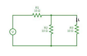
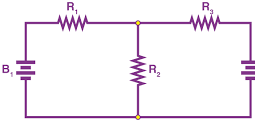
Current Division
For the circuit shown in Figure 3.18, the total circuit resistance RT is given by: Figure 3.18 : Current division circuit and Current Similarly, current Summarizing, with reference to Figure 3.18: Example 3.11 For the series-parallel arrangement shown in Figure 3.19, find (a) the supply current, (b) the current flowing through each resistor and (c) the voltage across each resistor. Figure…
-
Parallel Networks
shows three resistors, R1, R2 and R3 connected across each other, i.e., in parallel, across a battery source of V volts. Figure 3.9 : Parallel resistors In a parallel circuit: (a) the sum of the currents I1, I2 and I3 is equal to the total circuit current, I, i.e., I =I1 +I2 +I3, and (b) the source voltage, V volts, is the same across each of the resistors. From Ohm’s law: where R is the total circuit resistance. Since I =I1 +I2 +I3…
-
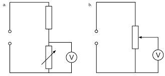
Potential Divider
The voltage distribution for the circuit shown in Figure 3.5(a) is given by: Figure 3.5 : Potential divider circuit The circuit shown in Figure 3.5(b) is often referred to as a potential divider circuit. Such a circuit can consist of a number of similar elements in series connected across a voltage source, voltages being taken from connections between the elements. Frequently the…
-
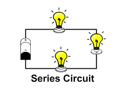
Series Circuits
shows three resistors R1, R2 and R3 connected end to end, i.e., in series, with a battery source of V volts. Since the circuit is closed, a current I will flow and the voltage across each resistor may be determined from the voltmeter readings V1, V2 and V3. Figure 3.1 : Series circuit In a series circuit: (a) the current I is the same in all parts of the circuit; therefore, the…