Category: Air Compressors
-
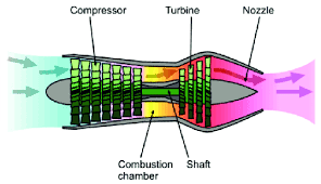
AXIAL FLOW COMPRESSORS
In axial flow compressors, the flow proceeds throughout the compressor in a direction essentially parallel to the axis of the machine. The unit consists of adjacent row of rotor blades and stator blades. One stage of the machine comprises a row of rotor blades followed by a row of stator blades. For efficient operation, the…
-
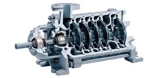
CENTRIFUGAL COMPRESSORS
In these compressors the pressure rise takes place due to the continuous conversion of angular momentum imparted to the gas by a high-speed impeller into static pressure. Unlike reciprocating compressors, centrifugal compressors are steady flow devices hence they are subjected to less vibration and noise. Figure 10.9 shows the working principle of a centrifugal compressor. As shown…
-
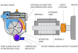
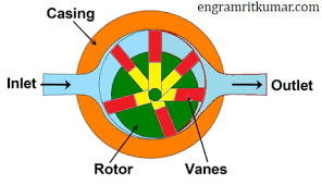
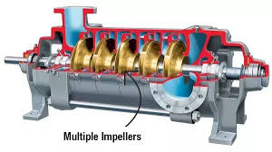
Multiple Vane Type Rotary Compressors
In multiple vane type compressors, the axis of rotation coincides with the centre of the roller (O); however, it is eccentric with respect to the centre of the cylinder (O’) as shown in Figure 10.8. The rotor consists of a number of slots with sliding vanes. During the running of the compressor, the sliding vanes are held…
-
Fixed Vane Type Compressors
These compressors belong to the category of positive displacement type as compression is achieved by reducing the volume of the gas. In this type of compressors, the rotating shaft of the roller has its axis of rotation that matches with the centre line of the cylinder; however, it is eccentric with respect to the roller…
-
Work Done in Multistage Compression
P−V and T−S diagrams for multistage compression are shown in Figure 10.6. Figure 10.6 ρ−V and T−S Diagrams for Multistage Compressor If P1, T1 and delivery pressure P3 are fixed, the optimum value of the intermediate pressure P2 for minimum work can be obtained by setting the derivative dW/dP2 = 0. For perfect cooling, In general, if there are N stages, the pressure ratio for each stage will be given by, Heat Rejected During…
-
Multistage Compression
Number of stages required depends on the pressure to be developed in compressor. Normally, following relationships are used with pressure and number of stages. Advantages of Multistage Compression Assumption in Multistage Compression: The following assumptions are usually made in calculation of work done in multistage compression:
-

Volumetric Efficiency
The volumetric efficiency of a compressor is the ratio of actual free air delivered to the displacement of the compressor. Substituting the value of V4 in Eq. (10.1), we get Where ∈ is clearance ratio and r is pressure ratio Example 10.1: A single cylinder, single acting air compressor has a cylinder diameter of 150 mm and stroke of 300 mm. It…
-

-
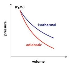
Polytropic Compression
Area 0−1−2−3 in Figure 10.4 represents the net work done, when the compression follows the polytropic law. Net work on air per cycle = Area 0−1−2−3 = Work done during compression (1−2) + Work done during air delivery (2−3) − Work done during suction (0−1). Similarly, for isentropic compression 10.3.2 Isothermal Compression In isothermal compression work done is minimum…
-

RECIPROCATING COMPRESSORS
In these compressors, the gas volume decreases and pressure increases due to the action of one or more reciprocating piston moving axially in one or more cylinders. It may be single acting or double acting, single cylinder or multicylinder and single stage or multistage compressors. Figure 10.2 shows the schematic of a reciprocating compressor. Reciprocating compressors…