In compound-wound DC generators, the field is produced by the shunt as well as series winding. Generally, the shunt field is stronger than the series field. When the series field assist the shunt field, the generator is called as cumulative compound-wound generator (see Fig. 11.21(a)). However, when the series field opposes the shunt field, the generator is known as differential compound-wound generator (see Fig. 11.21(b)).
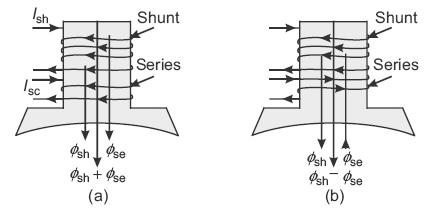
Fig. 11.21 (a) Cumulatively compound
(b) Differentially compound
Example 11.11
A 200 V, 8-pole, lap-connected DC shunt generator supplied 60, 40 W, 200 V lamps. It has armature and field circuit resistances of 0.2 Ω and 200 Ω, respectively. Calculate the generated emf, armature current, and current in each armature conductor.
(U.P.T.U. 2004–05)
The conventional circuit is shown in Figure 11.22.
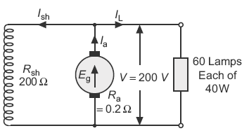
Fig. 11.22 Conventional diagram as per data
Here, V = 200 V; P = 8; A = P = 8 (lap winding);
Ra = 0.2 Ω; Rsh = 200 Ω
Load = 60 × 40 = 2,400 W
Load current, 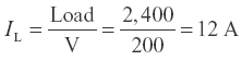
Shunt field current, 
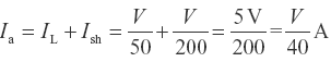
Armature current, Ia = IL + Ish
= 12 + 1 = 13 A
Generated emf, Eg = V + Ia Ra = 200 + 13 × 0.2
= 202.6 V
Current in each armature conductor, 
Example 11.12
A 20 kW, 200 V shunt generator has an armature resistance of 0.05 Ω and a shunt field resistance of 200 Ω. Calculate the power developed in the armature when it delivers rated output.
(U.P.T.U. 2006–07)
Solution:
The conventional circuit is shown in Figure 11.23.
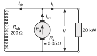
Fig. 11.23 Conventional diagram as per data
For shunt generator: Ia = IL + Ish
Power delivered to load, PL = VIL
Power developed in armature, Pg = EgIa
Now,
Ia = 100 + 1 = 101 A
Eg = V + Ia Ra = 200 + 101 × 0.05 = 205.05 V
Pg = Eg Ia = 205.05 × 101 = 20,710.05 W = 20.71 kW
Example 11.13
A 4-pole DC generator with wave-connected armature has 41 slots, and 12 conductors/slot. Armature resistance Ra = 0.5 Ω; shunt resistance is Rsh = 200 Ω; flux per pole = 125 mWb; and speed N = 1,000 rpm. Calculate voltage across 10 Ω load resistance across the armature terminal.
(U.P.T.U. 2007–08)
Solution:
The conventional circuit is shown in Figure 11.24.
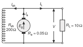
Fig. 11.24 Conventional diagram as per data
Here, P = 4; Ra = 0.5 Ω; Rsh = 200 Ω; ɸ = 125 mWb = 125 × 10−3 Wb; N = 1,000 rpm; RL = 10 Ω
Number of slots = 41
Number of conductors/slot = 12
Armature conductors, Z = 41 × 12 = 492
Number of parallel paths, A = 2 (wave winding)
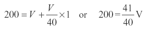
Generated emf, 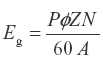
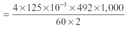
=2,050V
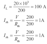
Load current, 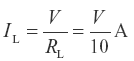
Shunt field current, 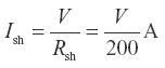
Armature current, 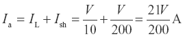
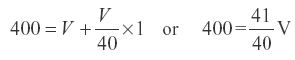
Eg = V + Ia Ra
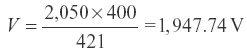
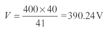
or
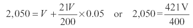
or
Example 11.14
A 4-pole DC shunt generator with wave-wound armature has 40 slots each having 12 conductors. Armature resistance is 1 Ω and shunt field resistance is 200 Ω. The flux per pole is 25 mWb. If a load of 50 Ω is connected across the armature terminals, calculate the voltage across the load when the generator is driven at 1,000 rpm. What will be the load voltage if the generator is lap wound?
(U.P.T.U. 2006–07)
Solution:
The conventional circuit is shown in Figure 11.25.
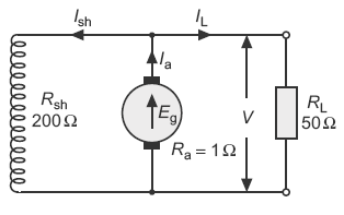
Fig. 11.25 Conventional diagram as per data
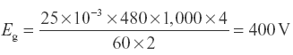
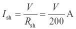
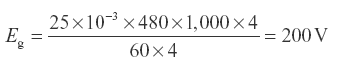
Here, P = 4, Ra = 1 Ω; Rsh = 200 Ω; ɸ = 25 mWb = 25 × 10−3 Wb; N = 1,000 rpm
Number of slots = 40; number of conductors/slot = 12
Total armature conductors,
Z = 40 × 12 = 480
Load resistance,
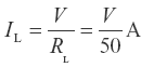
RL = 50 Ω
Number of parallel path, A = 2 (for wave winding)
Generated emf,

Load current,
Shunt field current,
Armature current,
Now,
Eg = V + Ia Ra
or
If the generator is lap wound, then A = P = 4
Eg = V + Ia Ra
or
or
Example 11.15
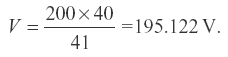
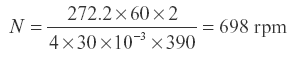
A 4-pole DC shunt generator with a wave-wound armature having 390 conductors has to supply a load of 500 lamps each of 100 W at 250 V. Allowing 10 V for the voltage drop in the connecting leads between the generator and the load and brush drop of 2 V. Calculate the speed at which the generator should be driven. The flux per pole is 30 mWb and the value of Ra = 0.05 Ω and Rsh = 65 Ω.
Solution:
The conventional circuit diagram of the DC shunt generator is shown in Figure 11.26.
Fig. 11.26 Conventional diagram as per data
Total load = 500 × 100 W
Voltage drop in leads, VL = 10 V
Voltage across shunt field winding,
Vsh = V + VL = 250 + 10 = 260 V
Ish = Vsh/Rsh = 260/65 = 4 A
Ia = IL + Ish = 200 + 4 = 204 A
Armature drop = Ia Ra = 204 × 0.05 = 10.2 V
Total brush drop, 2vb = 2 V
Generated emf, Eg = V + Ia Ra + VL + 2
= 250 + 10.2 + 10 + 2 = 272.2 V
Now,
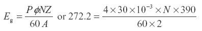
or
Example 11.16
A 4-pole DC shunt generator with a shunt field resistance of 100 Ω and an armature resistance of 1 Ω has 378 wave-connected conductors in its armature. The flux per pole is 0.02 Wb. If a load resistance of 10 Ω is connected across the armature terminals and the generator is driven at 1,000 rpm, calculate the power absorbed by the load.
Solution:
The conventional circuit is shown in Figure 11.27.
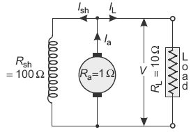
Fig. 11.27 Conventional diagram as per data
Generated emf, 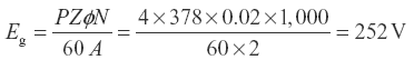
Line current,  (where V is terminal voltage)
Shunt field current, 
Armature current, ![]()
Using the relation, Eg = V + Ia Ra; 252 = V + 0.11 V × 1.0
Terminal voltage, V = 227 V
Load current,
Power absorbed by the load, P = VIL = 227 × 22.7 = 5.153 kW
Example 11.17
A short-shunt cumulative compound DC generator supplies 7.5 kW at 230 V. The shunt field, series field, and armature resistance are 100, 0.3 and 0.4 Ω, respectively. Calculate the induced emf and the load resistance.
Solution:
The conventional circuit is shown in Figure 11.28.
From Figure 11.29,
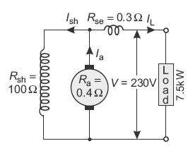
Fig. 11.28 Conventional diagram as per data
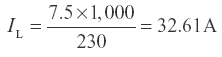
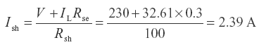
Ia = IL + Ish = 32.61 + 2.39 = 35 A
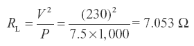
Induced emf, Eg = V + IL Rse + Ia Ra
= 230 + 32.61 × 0.3 + 35 × 0.4 = 253.78 V
Load resistance,
Example 11.18
A 20 kW compound generator works on full-load with a terminal voltage of 230 V. The armature, series, and shunt field resistance are 0.1, 0.05, and 115 Ω, respectively. Calculate the generated emf when the generator is connected as shunt.
(Pb. Univ. Dec. 1994)
Solution:
The conventional circuit is shown in Figure 11.29.
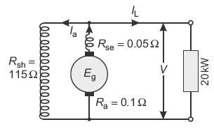
Fig. 11.29 Conventional diagram as per data
Load = 20 kW = 20 × 103 W
V = 230 V; Ra = 0.1 Ω; Rse = 0.05 Ω
Line current,
Shunt field current,
Armature current, Ia = IL + Ish = 86.96 + 2 = 88.96 A
Generated emf, Eg = V + Ia Ra + Ia Rse
= 230 + 88.96 × 0.1 + 88.96 × 0.05
= 243.3 V
Leave a Reply