
The rotor circuit diagram of an induction motor is shown in Figure 12.12.
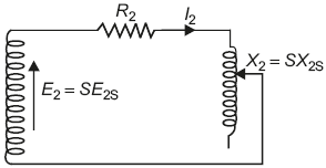
Fig. 12.12 Rotor circuit of an induction motor as per its parameters
Under running condition
Rotor-induced emf = E2 = S × E2s
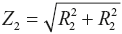
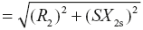
Rotor impedance,
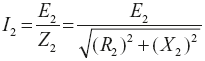
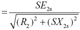
Rotor current,
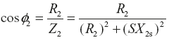
Rotor power factor,
Leave a Reply