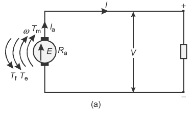
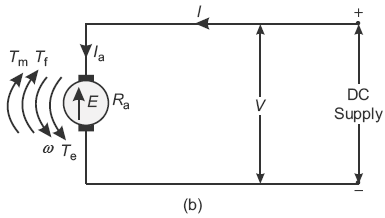
It has been seen that the same machine can be used as a DC generator or as a DC motor. When it converts mechanical energy (or power) into electrical energy (or power), it is called a DC generator and when it is used for reversed operation, it is called a DC motor. Table 11.1 gives the comparison between the generator and the motor action.
Table 11.1 Comparison between the Generator and the Motor Action
Example 11.19
A 50 H.P., 400 V, 4-pole, 1,000 rpm, DC motor has flux per pole equal to 0.027 Wb. The armature having 1,600 conductors is wave connected. Calculate the gross torque when the motor takes 70 A.
Solution:
Torque developed, 
where P = 4; ɸ = 0.027 Wb; Z = 1,600; Ia = 70 A; A = 2 (wave connected)

Example 11.20
The induced emf in a DC machine is 200 V at a speed of 1,200 rpm. Calculate the electromagnetic torque developed at an armature current of 15 A.
Solution:
Here, Eb = 200 V; N = 1,200 rpm; Ia = 15 A
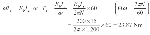
Now, power developed in the armature,
Example 11.21
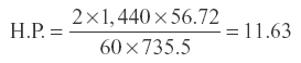
A 4-pole DC motor has a wave-wound armature with 594 conductors. The armature current is 40 A and flux per pole is 7.5 mWb. Calculate H.P. of the motor when running at 1,440 rpm.
Solution:
Torque developed,

Power developed = ω T watt, where 

or
Example 11.22
A 6-pole, lap-wound DC motor takes 340 A when the speed is 400 rpm. The flux per pole is 0.05 Wb and the armature has 864 turns. Neglecting mechanical losses, calculate the BHP of the motor.
(P.T.U. May 2010)
Solution:
Here, P = 6; A = P = 6 (lap wound); IL = 340 A; N = 400 rpm,
ɸ = 0.05 Wb; number of turns = 864
Z = 864 × 2 = 1,728
Back emf, 
Armature current, Ia = IL = 340 A
Power developed = Eb × Ia = 576 × 340 = 195,840 W
Neglecting losses, 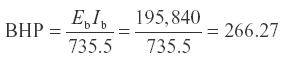
11.20 TYPES OF DC MOTORS
On the basis of the connections of armature and their field winding, DC motors can be classified as follows.
11.20.1 Separately Excited DC Motors
The conventional diagram of a separately excited DC motor is shown Figure 11.40. Its voltage equation will be
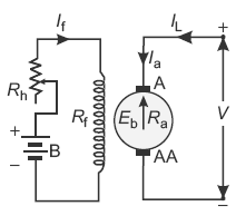
Fig. 11.40 Conventional diagram of a separately excited DC motor
Eb = V − Ia Ra − 2vb (where vb is voltage drop per brush)
11.20.2 Self-excited DC Motors
These motors can be further classified as follows:
- Shunt motors: Their conventional diagram is shown in Figure 11.41.
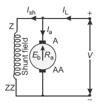 Fig. 11.41 Conventional diagram of a shunt wound DC motorImportant relations: Ish = V/Rsh; Ia = IL − IshEb = V − Ia Ra − 2vb (where vb is voltage drop per brush)
 - Series motor: Its conventional diagram is shown in Figure 11.42.
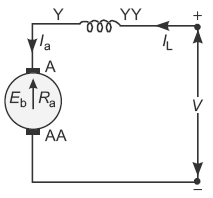 Fig. 11.42 Conventional diagram of a series wound DC motorImportant relations: IL = Ia = Ise; Eb = V − Ia (Ra + Rse) − 2vb
 - Compound motor: Its conventional diagram (for long shunt) is shown in Figure 11.43.
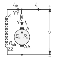 Fig. 11.43 Conventional diagram of a compound wound DC motor
 In all the above mentioned voltage equations, the brush voltage drop vb is sometimes neglected since its value is very small.The compound motor can be further subdivided as follows:
- Cumulative compound motors: In these motors, the flux produced by both the windings is in the same direction, that is, ɸr = ɸsh + ɸse
- Differential compound motors: In these motors, the flux produced by the series field winding is opposite to the flux produced by the shunt field winding, that is, ɸr = ɸsh − ɸse
Example 11.23
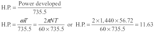
A 4-pole DC motor has a wave-wound armature with 594 conductors. The armature current is 40 A and flux per pole is 7.5 mWb. Calculate H.P. of the motor when running at 1,440 rpm
Solution:
Torque developed,

Power developed = ωT watts, where 
Example 11.24
A 6-pole lap-wound shunt motor has 500 conductors in the armature. The resistance of armature path is 0.05 Ω. The resistance of shunt field is 25 Ω. Find the speed of the motor when it takes 120 A from a DC mains of 100 V supply. Flux per pole is 2 × 10⁻² Wb.
Solution:
The conventional diagram of the motor is shown in Figure 11.44
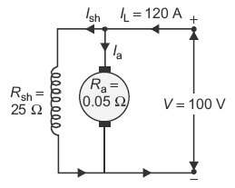
Fig. 11.44 Conventional diagram as per data
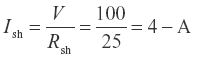
Ia = IL − Ish = 120 − 4 = 116 − A
Eb = V − Ia Ra
Now,

or
N = 565.2 rpm
Example 11.25
A 6-pole, 440 V DC motor has 936 wave-wound armature conductors. The useful flux per pole is 25 mWb. The torque developed is 45.5 kgm. If armature resistance is 0.5 Ω, then calculate (i) armature current and (ii) speed.
(P.T.U.)
Solution:
Number of poles, P = 6
Number of armature conductors, Z = 936
Flux per pole, ɸ = 25 mWb = 25 × 10−3 Wb
Number of parallel path, A = 2 (wave-wound armature)
Terminal voltage, V = 440 V
Armature resistance, Ra = 0.5 Ω
Torque developed, T = 45.5 kgm = 45.5 × 9.81 = 446.35 Nm
- Using the relation,
 Armature current,
- Induced emf, E = V − Ia Ra (motor action) = 440 − 39.95 × 0.5 = 420 V
Using the relation, ωT = EIa or 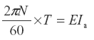
Speed

Example 11.26
A 400 V DC motor takes an armature current of 100 A when its speed is 1,000 rpm. If the armature resistance is 0.25 Ω, then calculate the torque produced in Nm.
(P.T.U.)
Solution:
Terminal voltage, V = 400 V
Armature current, Ia = 100 A
Armature resistance, Ra = 0.25 Ω
Speed, N = 1,000 rpm
Induced emf, E = V − Ia Ra (motor action)
= 400 − 100 × 0.25 = 375 V
Using the relation, ωT = EIa or 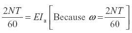
Therefore, torque produced, 
Example 11.27
The electromagnetic torque developed in a DC machine is 80 Nm for an armature current of 30 A. What will be the torque for a current of 15 A? Assume constant flux. What is the induced emf at a speed of 900 rpm and an armature current of 15 A?
Solution:
Torque developed, T1 = 80 Nm
Armature current, Ia1 = 30 A
Armature current, Ia2 = 15 A
Let the torque developed is T2 Nm when the armature current is 15 A.
Now,
T ∝ fIa
When flux f is constant, T ∝ Ia
Let the torque developed is T2 Nm when the armature current is 15 A.
Now,
T α ɸIa
When flux ɸ is constant, T ∝ Ia
Therefore,

or
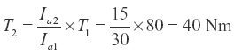
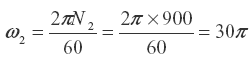
Power developed in the armature = E2Ia2 = ω2T2
where

Leave a Reply