For simplicity, consider only one coil AB placed in the strong magnetic field. The two ends of the coil are joined to slip rings A′ and B′, respectively. Two brushes rest on these slip rings, as shown in Figure 11.10.
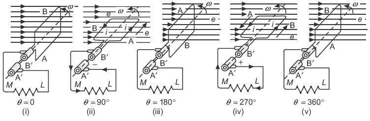
Fig. 11.10 Direction of induced emf/current in internal and external circuit of rotating coil at different instants using two slip-rings
When this coil is rotated in counter clockwise direction at an angular velocity of ω radians/s, the magnetic flux is cut by the coil and an emf is induced in it. The position of the coil at various instants is shown in Figure 11.10 and the corresponding value of the induced emf and its direction is shown in Figure 11.11. The induced emf is alternating and the current flowing through the external resistance is also alternating, that is, at the second instant, current flows in external resistance from M to L; while at the fourth instant, it flows from L to M as shown in Figure 11.11.
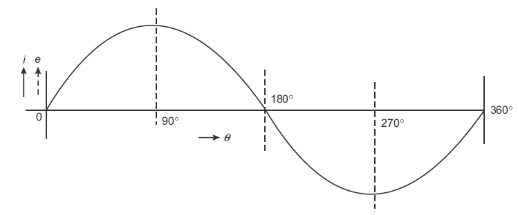
Fig. 11.11 Graphical representation of current in external circuit at various instants
11.6.1 Commutator Action
Now, consider that the two ends of the coil are connected to only one slip ring split into two parts (segment), that is, A″ and B″. Each part is insulated from the other by a mica layer. Two brushes rest on these parts of the ring as shown in Figure 11.12.
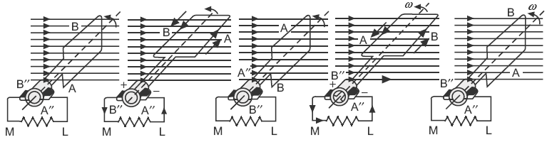
Fig. 11.12 Direction of induced emf/current in internal and external circuit of a rotating coil at different instants using split-ring
In this case, when the coil is rotated in counter clockwise direction at an angular velocity of ω radians/s, the magnetic flux is cut by the coil and an emf is induced in it. The magnitude of emf induced in the coil at various instants will remain the same as shown in Figure 11.13.
However, the flow of current in the external resistor or circuit will become unidirectional, that is, at the second instant, the flow of current in the external resistor is from M to L as well as the flow of current in the external resistor is from M to L in the fourth instant, as shown in Figure 11.12. Its wave shape is shown in Figure 11.13.
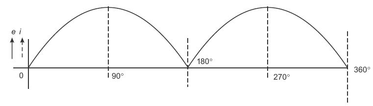
Fig. 11.13 Graphical representation of current in external circuit at various instants
Hence, an AC is converted into unidirectional current in the external circuit with the help of a split ring (i.e., commutator).
In an actual machine, there are number of coils connected to the number of segments of the ring called commutator. The emf or current delivered by these coils to the external load is shown in Figure 11.14(a). The actual flow of current flowing in the external load is shown by the firm line that fluctuates slightly. The number of coils placed on the armature are even much more than this and a pure DC is obtained at the output as shown in Figure 11.14(b).
Thus, in actual machine working as a generator, the function of commutator is to convert the AC produced in the armature into DC in the external circuit.
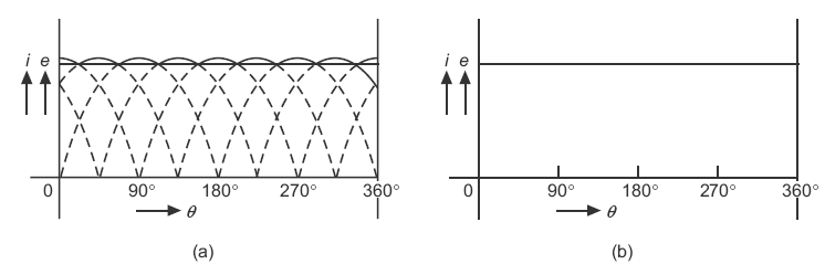
Fig. 11.14 (a) Pulsating current in external circuit using number of coils (b) Graphical representation of actual current in external circuit of a DC generator
11.7 EMF EQUATION
Let P = number of poles of the machine
ɸ = flux per pole in Wb
Z = total number of armature conductors
A = number of parallel paths in the armature winding
In one revolution of the armature, flux cut by one conductor = PɸWb
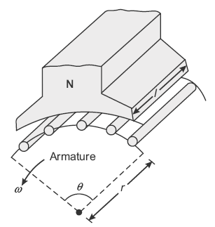
Fig. 11.15 No. of conductors under the influence of one pole
Time taken to complete one revolution, t = 60/N s
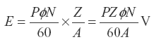
Therefore, average induced emf in one conductor is
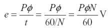
The number of conductors connected in series in each parallel path = Z/A
Therefore, average induced emf across each parallel path or across the armature terminals
or
 where n is the speed in r.p.s, that is,
For a given machine, the number of poles and number of conductors per parallel path (Z/A) are constant.
E = Kɸn where  is a constant or E ∝ ɸn
or
E = K1ɸN where  is another constant or E ∝ ɸN
or
E ∝ ɸω, where  is the angular velocity in radian/s
Thus, we conclude that the induced emf is directly proportional to flux per pole and speed. Moreover, the polarity of the induced emf depends upon the direction of magnetic field and the direction of rotation. If either of the two is reversed, the polarity of induced emf, that is, brushes is reversed; however, when both are reversed, the polarity does not change.
This induced emf is fundamental phenomenon to all DC machines whether they are working as a generator or motor. However, when the machine is working as a generator, this induced emf is called generated emf and is represented as Eg, i.e., 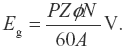
Example 11.1
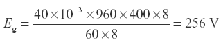
An 8-pole lap-wound DC generator has 960 conductors, a flux of 40 mWb per pole and is driven at 400 rpm. Find OC emf.
Solution:
Open-circuit emf, 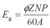
where ɸ = 40 mWb = 40×10−3 Wb; Z = 960; N = 400 rpm; P = 8
Example 11.2
Calculate the voltage induced in the armature winding of a 4-pole, wave wound DC machine having 500 conductors and running at 1,000 rpm. The flux per pole is 30 mWb.
(P.T.U. May 2000)
Solution:
Here,
P = 4; A = 2 (wave wound); Z = 728; N = 1,800 rpm
ɸ = 35 mWb = 35 × 10−3 Wb
Generated voltage,

Example 11.3
A 4-pole, lap-wound armature has 144 slots with two coil sides per slot, where each coil has two turns. If the flux per pole is 20 mWb and the armature rotates at 720 rpm, what is the induced emf (i) across the armature and (ii) across each parallel path?
(PTU May 2001)
Solution:
Here, P = 4; A = P = 4 (lap wound); ɸ = 20 mWb = 20 × 10−13 Wb; N = 720 rpm
Number of slots = 144 with two coil sides per slot and each coil has two turns
Therefore, Z = 144 × 2 × 2 = 576
Induced emf across armature, 
Voltage across each parallel path = Eg = 138.24 V
Example 11.4
A 6-pole machine has an armature with 90 slots and 8 conductors per slot, the flux per pole is 0.05 Wb and rms at 1,000 rpm. Determine induced emf if winding is (i) lap connected and (ii) wave connected.
(U.P.T.U. May 2003)
Solution:
Here, P = 6; ɸ = 0.05 Wb; N = 1,000 rpm
Number of slots = 90 with each slot having 8 conductors
Therefore,
Z = 90 × 8 = 720
- When lap connected: A = P = 6Induced emf,

- When wave connected: A = 2Induced emf,

Example 11.5
An 8-pole DC generator has 600 armature conductors and a useful flux of 0.06 Wb. What will be the emf generated if it is lap wound and runs at 1,000 rpm? What must be the speed at which it is to be driven to induce the same voltage if it is wave wound?
(U.P.T.U. May 2001, Type)
Solution:
Here, P = 8; Z = 600; ɸ = 0.06 Wb; N = 1,000 rpm
A = P = 8 (when lap wound)
Induced emf,

when wave wound, let the speed be N′ rpm but Eg = 600 V
Now,

Example 11.6
A wave-wound armature of an 8-pole generator has 51 slots. Each slot contains 16 conductors. The voltage required to be generated is 300 V. What would be the speed of coupled prime mover if flux per pole is 0.05 Wb?
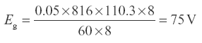
If the armature is rewound as lap-wound machine and run by same prime mover, what will be the generated voltage?
(Univ. Question)
Solution:
Here, P = 8; ɸ = 0.05 Wb; number of slots = 51; conductors per slot = 16
Therefore, Z = 51 × 16 = 816
When the machine is wave wound, A = 2 and Eg = 300 V
Now,

Therefore, speed
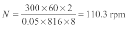
When the machine is rewound as lap winding, A = P = 8 and N = 110.3 rpm
Example 11.7
A 6-pole, lap-wound armature rotating at 350 rpm is required to generate 260 V. The effective flux per pole is about 0.05 Wb. If the armature has 120 slots, determine the suitable number of conductors per slot, and hence, determine the actual value of flux required to generate the same voltage.
(A.M.I.E. Summer 2001)
Solution:
Here, P = 6; A = P = 6; N = 350 rpm; Eg = 260 V; ɸ = 0.05 Wb

or
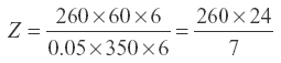

For 8 conductors or slot, Z = 120 × 8 = 960
Actual value of flux required, 
Example 11.8
The emf generated by a 4-pole DC generator is 400 V, when the armature is driven at 1,200 rpm. Calculate the flux per pole if the wave-wound generator has 39 slots having 16 conductors per slot.
Solution:
Induced emf,
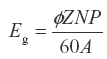
where P = 4; Eg = 400 V; N = 1,200 rpm; Z = 39 × 16 = 624; A = 2 (wave winding)
Therefore, flux per pole, 
Example 11.9
The armature of a 4-pole 250 V, lap-wound generator has 500 conductors and rms of 400 rpm. Determine the useful flux per pole. If the number of turns in each field coil is 1,000, what is the average induced emf in each field coil on breaking its connection if the magnetic flux set-up by it dies away completely in 0.1 s?
(A.P. Univ. May 2006)
Solution:
Here, P = 4; Eg = 250 V; Z = 500; A = P = 4; N = 400 rpm

Number of turns of exciting winding, Nt = 1,000

Example 11.10
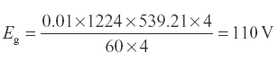
A 4-pole generator with wave-wound armature has 51 slots, each having 24 conductors. The flux per pole is 0.01 Wb. At what speed must the armature rotate to give an induced emf of 220 V? What will be the emf developed if the winding is lap connected and the armature rotates at the same speed?
Induced emf, 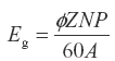
where ɸ = 0.01 Wb; Z = 51 × 24 = 1,224; E = 220 V; P = 4; A = 2 (wave winding).

For lap winding, A = P = 4
Leave a Reply