
The various parameters and electrical quantities are represented on the circuit diagram, as shown in Figure 12.13. The rotor current is given by the following expression:
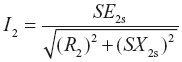
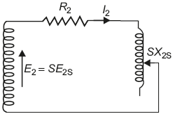
Fig. 12.13 Rotor circuit
The other expression for the rotor current is
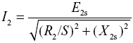 (dividing the numerator and denominator by S)
This expression gives a convenient form of equivalent circuit as shown in Figure 12.14.
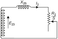
Fig. 12.14 Equivalent rotor circuit
The resistance is a function of slip and can be split into two parts; 
where  represents electrical load on the rotor.
Therefore, the final simplified equivalent rotor circuit is shown in Figure 12.15(a). Where R2 is rotor resistance and X2s is standstill leakage reactance. The resistance  is fictitious resistance representing load.
The power consumed by this fictitious resistance, that is,  is the electrical power, which is converted into mechanical power to pick the load. After subtracting the mechanical losses, we get the output power available at the shaft.
Therefore, electrical power converted into mechanical power = 
From the simplified equivalent circuit, the phasor diagram of rotor circuit is drawn as shown in Figure 12.15(b).
Rotor current I2 lags behind the rotor standstill induced emf E2s by an angle ɸ.
The voltage drop across R2, that is, I2R2 and across that is,  are in phase with current I2, whereas the voltage drop in X2s, that is, I2X2s leads the current I2 by 90°.
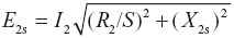
The vector sum of all the three drops is equal to E2s, that is,
Power factor of rotor circuit,
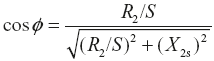
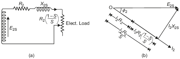
Fig. 12.15 (a) Simplified rotor circuit (b) Phasor diagram for rotor circuit
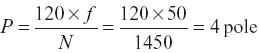
A three-phase, 440 V, 50 H.P., 50 Hz induction motor runs at 1450 rpm, when it delivers rated output power. Determine: (i) number of poles in the machine, (ii) speed of rotating air gap field, (iii) rotor-induced voltage if stator to rotor turns ratio is 1:0.80. Assume the winding factors are the same, and (iv) frequency of rotor current.
(U.P.T.U. 2004–05)
Solution:
- No. of poles,
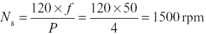
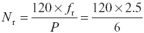
- Speed of rotating air gap field,
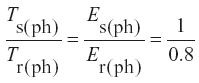 Er(ph) = 0.8 × Es(ph) = 0.8 × 440 = 342 V
 - Frequency of rotor currents, fr = S × fWhere
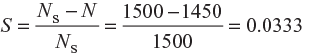 ∴fr = 0.0333 × 50 = 1.665 Hz
Example 12.10
A three-phase, 50 Hz induction motor has six poles and operates with a slip of 5% at a certain load. Determine (i) the speed of the rotor with respect to the stator, (ii) the frequency of rotor current, (iii) the speed of the rotor magnetic field with respect to rotor, (iv) the speed of the rotor magnetic field with respect to stator, and (v) the speed of the rotor magnetic field with respect to the stator magnetic field.
(U.P.T.U. Feb. 2002)
Solution:
Supply frequency, f = 50 Hz
Number of poles, P = 6
Slip,
S = 5% = 0.05
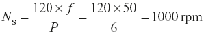
Synchronous speed, 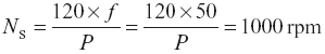
- Speed of rotor with respect to the stator, N = NS × (1 − S) = 1000 × (1 − 0.05) = 950 rpm
- Frequency of rotor current, ƒr = S × f = 0.05 × 50 = 2.5 Hz
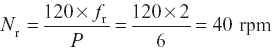
- Speed of rotor magnetic field with respect to the rotor
 = 50 rpm
 - Speed of rotor magnetic field with respect to the stator = N + Nr = 950 + 50 = 1000 rpm
- Rotor field and stator field are revolving at the same speed of 1000 rpm, and therefore, speed of rotor field with respect to stator field is zero.
A three-phase, 50 Hz induction motor has a full-load speed of 960 rpm. Calculate (i) slip, (ii) number of poles, (iii) frequency of the rotor-induced emf, (iv) speed of the rotor field with respect to rotor structure, (v) speed of rotor field with respect to stator structure, and (vi) speed of rotor field with respect to the stator field.
(U.P.T.U. Tut)
Solution:
Supply frequency, f = 50 Hz
Full-load running speed, N = 960 rpm
All the machines have even number of poles such as 2, 4, 6, 8, …
When, P = 2, NS= 3000 rpm; P = 4, NS = 1500 rpm; P = 6, NS = 1000 rpm
P = 8, NS = 750 rpm.
The nearest synchronous speed more than 960 rpm is 1000 rpm, and therefore, P = 6
- Slip,
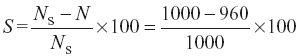 = 4% = 0.04
 - Frequency of rotor-induced emf, ƒr = S × f = 0.04 × 50 = 2Hz
- Speed of the rotor field with respect to rotor structure
- Speed of the rotor field with respect to stator structure = Speed of rotor + speed of rotor field with respect to rotor structure = N + Nr = 960 + 40 = 1000 rpm
- Rotor field and stator field are revolving at the same of 1000 rpm, and therefore, speed of rotor field with respect to stator field is zero.
Example 12.12
A balanced, three-phase, 50 c/s voltage is applied to a three-phase, four-pole induction motor. When the motor delivers rated output, the slip is found to be 0.05. Determine (i) the speed of the revolving field relative to the stator structure, (ii) the frequency of the rotor currents, (iii) the speed of the rotor mmf relative to the rotor structure, (iv) the speed of the rotor mmf relative to the stator structure, (v) the speed of the rotor mmf relative to the stator field distribution, and (vi) are the conditions right for the development of the net unidirectional torque?
(P.T.U.)
Solution:
Here, P = 4, f = 50 Hz, S = 0.05
- The speed of the revolving field relative to the stator structurethat is,
- ƒr = S × ƒ = 0.05 × 50 =2.5 Hz
- The speed of rotor mmf relative to the rotor structure,
- Rotor speed, N = Ns × (1 − S) = 1500 × (1 − 0.05) = 1425 rpmThe speed of the rotor mmf relative to the stator structure = N + Nr = 1425 + 75 =1500 rpm
- The speed of the rotor mmf relative to the stator field distribution = Ns − (N + Nr) = 1500 − 1500 = 0
- Yes. The given conditions completely satisfy the development of net unidirectional torque.
Example 12.13
A three-phase induction motor has a rotor for which the resistance per phase is 0.1Ω and reactance per phase when stationary is 0.4Ω. The rotor-induced emf per phase is 100V when stationary. Calculate rotor current and rotor p.f. (i) when rotor is stationary and (ii) when running with a slip of 5%.
(P.T.U.)
Solution:
Here, R2 = 0.1 Ω; X2s = 0.4 Ω; E2s = 100 V
- When the rotor is stationaryRotor current,
 Rotor power factors,
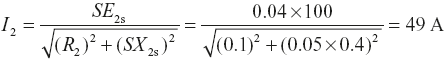
- When rotor is running with a slip of 5%, that is, S = 0.05Rotor current,
 Rotor power factor,
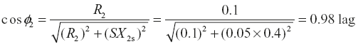
Leave a Reply