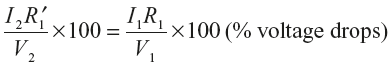
In an actual transformer, the primary and secondary windings have some resistance represented by R1 and R2, respectively. These resistances are shown external to the windings in Figure 10.19. The resistance of the two windings can be transferred to either side in order to simplify the calculations. The resistance is transferred from one side to the other in such a manner that percentage voltage drop remains the same when represented on either side.
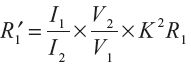
Let the primary resistance R1 be transferred to the secondary side and the new value of this resistance be ![]() called equivalent resistance of primary referred to secondary side as shown in Figure 10.20(a). I1 and I2 be the full-load primary and secondary currents, respectively.
called equivalent resistance of primary referred to secondary side as shown in Figure 10.20(a). I1 and I2 be the full-load primary and secondary currents, respectively.
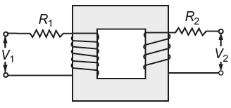
Fig. 10.19 Transformer with its windings resistances
Then,
or
∴ Total equivalent resistance referred to secondary.
Res = R2 + ![]() = R2 + K2R1
= R2 + K2R1
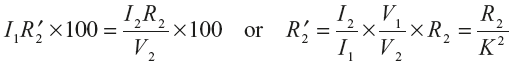
Now consider resistance R2, when it is transferred to primary, let its new value be ![]() called equivalent resistance of secondary referred to primary as shown in Figure 10.20(c).
called equivalent resistance of secondary referred to primary as shown in Figure 10.20(c).
Then,
∴ Total equivalent resistance referred to primary,
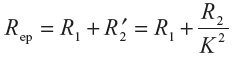
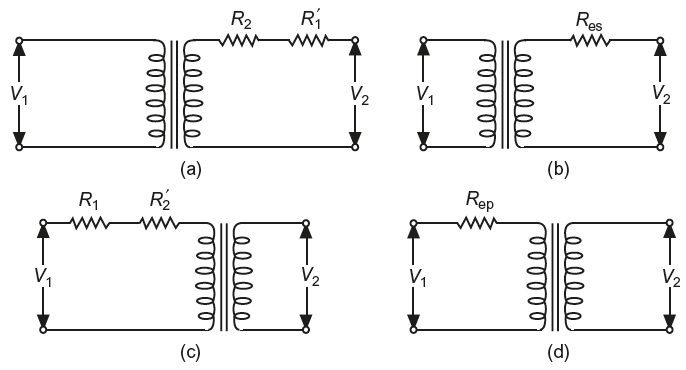
Fig. 10.20 (a) and (b) Equivalent resistance when referred to secondary side (c) and (d) Equivalent resistance when referred to primary side
10.12 MUTUAL AND LEAKAGE FLUXES
So far, it is assumed that when AC supply is given to the primary winding of a transformer, an alternating flux is set up in the core and whole of this flux links with both primary and secondary windings. However, in an actual transformer, both the windings produce some flux that links only with the winding that produces it.
The flux that links with both windings of the transformer is called mutual flux and the flux that links only with one winding of the transformer and not to the other is called leakage flux.
The primary ampere turns produce some flux ɸl1 which is set up in air and links only with primary winding as shown in Figure 10.21(a), is called primary leakage flux.
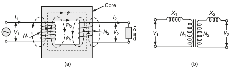
Fig. 10.21 (a) Representation of leakage flux on primary and secondary side (b) Representation of primary and secondary reactances
Similarly, secondary ampere turns produce some flux ɸl2 which is set up in air and links only with secondary winding is called secondary leakage flux.
The primary leakage flux ɸl1 is proportional to the primary current I1 and secondary leakage flux ɸl2 is proportional to secondary current I2. The primary leakage flux ɸl1 produces self-inductance L1(= N1ɸ1/ I1) which in turn produces leakage reactance X1(=2π fL1). Similarly, secondary leakage flux ɸl2 produces leakage reactance X2(=2π fL2). The leakage reactance (inductive) has been shown external to the windings in Figure 10.21(b).
Leave a Reply