
Metal curtain wall systems can be classified according to their degree or mode of assembly at the time of installation on the building (Figure 21.10). Many metal-and-glass curtain walls are furnished as stick systems whose principal components are metal mullions and rectangular panels of glass and spandrel material that are assembled in place on the building (Figure 21.10a). Stick systems have the advantages of low shipping bulk and high degree of adjustability to unforeseen site conditions, but they must be assembled on site, under highly variable conditions, rather than in a factory with its ideal tooling, controlled environmental conditions, and lower wage rates. Aluminum entrances and storefronts are also typically installed as stick systems.
The unit system of curtain wall installation takes full advantage of factory assembly and minimizes onsite labor, but the units require more space during shipping and more protection from damage than stick system components (Figure 21.10b). The unit-and-mullion system (Figure 21.10c), which is seldom used today, offers a middle ground between the stick and unit systems.
The panel system (Figure 21.10d) is made up of homogeneous units that are formed from metal sheet. Its advantages and disadvantages are similar to those of the unit system, but its production involves the higher tooling costs of a custom-made die or mold, which makes it advantageous only for a building that requires a large number of identical panels.
The column-cover-and-spandrel system (Figure 21.10e) emphasizes the structural module of the building rather than creating its own grid on the facade, as the previously described systems do. A custom design must be created for each project because there is no standard column or floor spacing for buildings. Special care is required in detailing the spandrel panel support to ensure that the panels do not deflect when loads are applied to the spandrel beams of the building frame; otherwise, the window strips could be subjected to loadings that would deform the mullions and crack the glass.
Outside Glazing and Inside Glazing
A metal cladding system may be designed to be outside glazed, which means that glass must be installed or replaced by workers standing on scaffolding or staging outside the building. Alternatively, it may be designed to be inside glazed by workers who stand inside the building. Inside glazing is more convenient and is more economical for a tall building, but it requires a somewhat more elaborate set of extrusions. Outside glazing systems utilize a relatively simple set of shapes and are less expensive for a building that is only one to three stories tall. Some curtain wall systems are designed so that they may be glazed from either side.
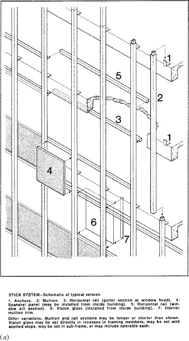
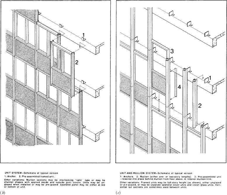
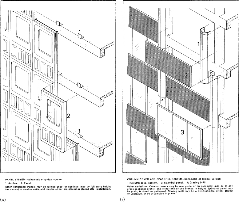
FIGURE 21.10 Modes of assembly for curtain walls. (a) Stick system. (b) Unit system. (c) Unit-and-mullion system. (d) Panel system. (e) Column-cover-and-spandrel system. (Reprinted with permission from AAMA Aluminum Curtain Wall Design Guide)
An Outside Glazed Curtain Wall System
An off-the-shelf, externally glazed stick system for aluminum-and-glass curtain walls is illustrated in Figures 21.11–21.16. This system is suitable for a low building whose walls workers can easily reach from external scaffolding.
An Inside Glazed Curtain Wall System
An off-the-shelf, internally glazed stick system for aluminum-and-glass curtain walls is illustrated in Figures 21.17–21.23. This system is suitable for use on tall buildings, because it is installed entirely by workers who stand inside the building. Replacement of glass may also be done from within the building.
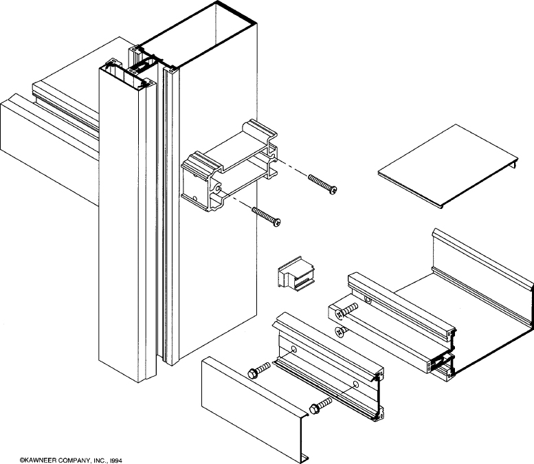
FIGURE 21.11 The Kawneer 1600 System1® is an outside glazed stick system. Vertical mullions that run continuously from floor to floor support discontinuous horizontal mullions that are connected to them by means of shear blocks and screws. Each light of glass sits on two rubber glazing blocks in the gutter of the horizontal mullion (not shown in this drawing). The inner surface of the glass rests against extruded rubber glazing gaskets pressed into small channels in both the vertical and horizontal mullions. Extruded aluminum pressure plates with rubber glazing gaskets are applied to both horizontal and vertical mullions to clamp the glass into place and create a weathertight seal. Each pressure plate is attached by means of screws that pass through drilled holes into an extruded screw slot. A thick rubber gasket in the screw slot acts as a thermal break. Snap-on covers conceal the screw heads and give a neat exterior appearance. A molded rubber plug at either end of each horizontal mullion contains any leakage or condensate within the horizontal mullion, from which it escapes via -inch-diameter (8-mm) weep holes (not shown here) drilled through the pressure plate and the bottom edge of the snap-on cover. Figures 21.11–21.15 further illustrate this system. (All the drawings of this system in Figures 21.11–21.14 are courtesy of Kawneer Company, Inc.)
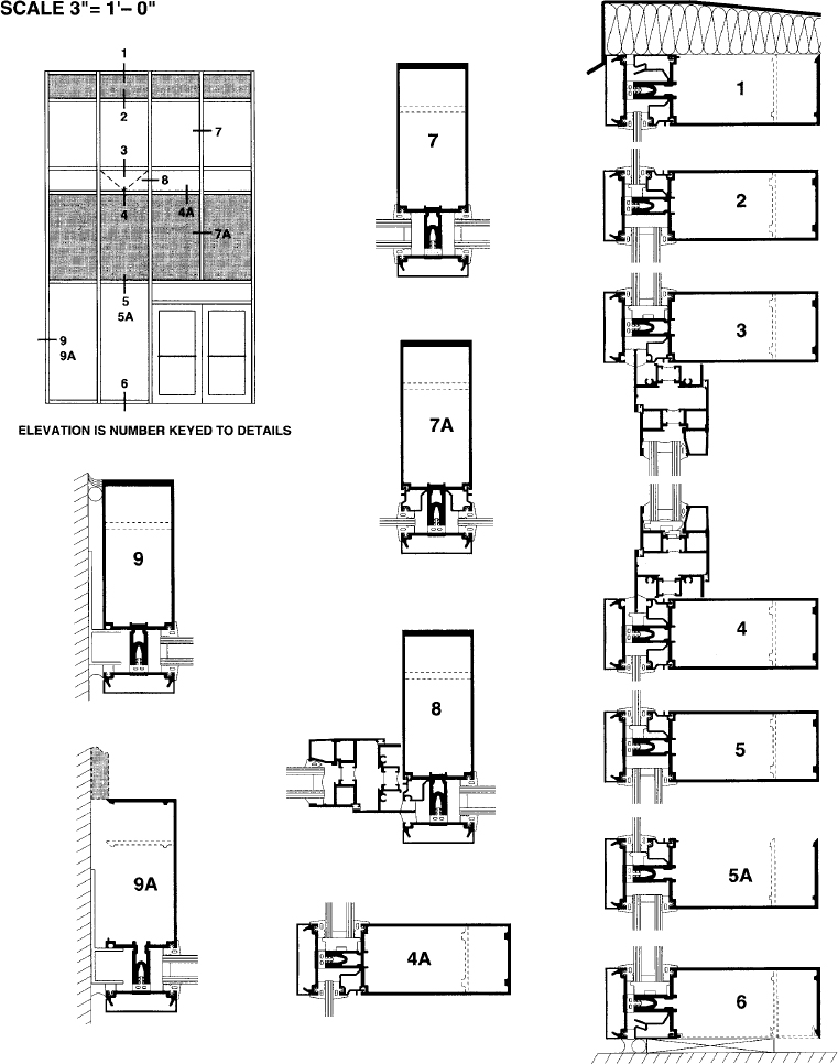
FIGURE 21.12 The manufacturer’s details for the Kawneer 1600 System1 curtain wall are all keyed to the small elevation view at the upper left corner of this page. The details are reproduced here at one-quarter of their actual size.
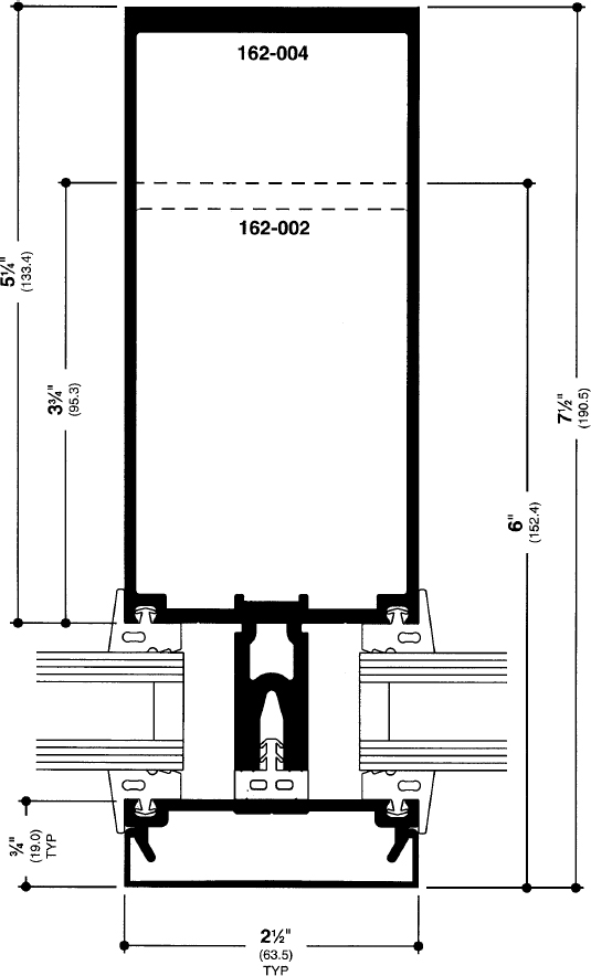
FIGURE 21.13 In this full-size detail of the vertical mullion for the Kawneer 1600 System1, we see that the basic extrusion is a rectangular box shape that is structurally stiff and presents a neat appearance inside the building. The broken lines indicate a smaller box mullion (162-002) that may be used for buildings with shorter floor-to-floor heights or smaller wind loads. The extruded plastic thermal break attaches to the mullion with a projecting “pine tree” spline that is pushed into the screw slot. Holes are drilled through the thermal break for the screws (not shown) that attach the pressure plate. The four rubber glazing gaskets attach to the aluminum pieces with projecting splines.
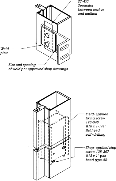
FIGURE 21.14 Vertical mullions of the Kawneer 1600 System1 are attached to the edges of the building’s floors with the angle anchor shown in the top drawing. Sections of vertical mullion are spliced with the aluminum internal spline shown in the lower drawing. The spline is screwed to the lower section of mullion but the upper section is free to slide, which allows for thermal expansion and contraction.
FIGURE 21.15 Two different horizontal mullion extrusions are available for the Kawneer 1600 System1. The closed extrusion (top) is used in most situations. The open-back extrusion (bottom) allows access to the shear block on the vertical mullion for purposes of assembly; it is used for portions of the wall that butt against other materials, such as heads, sills, and end bays. A snap-on cover closes the open back of the mullion, leaving only a virtually invisible seam. Rubber setting blocks are shown beneath the edges of the glass in both mullions. In the upper-left corner of the upper detail, a small aluminum extrusion has been added to allow the mullion to hold a single layer of spandrel glass or vision glass rather than the standard 1-inch (25-mm) double-glazing assembly. Weep holes are not shown; they are drilled horizontally through the pressure plate just above the thermal break and vertically through the bottom edge of the outside snap-on cover.
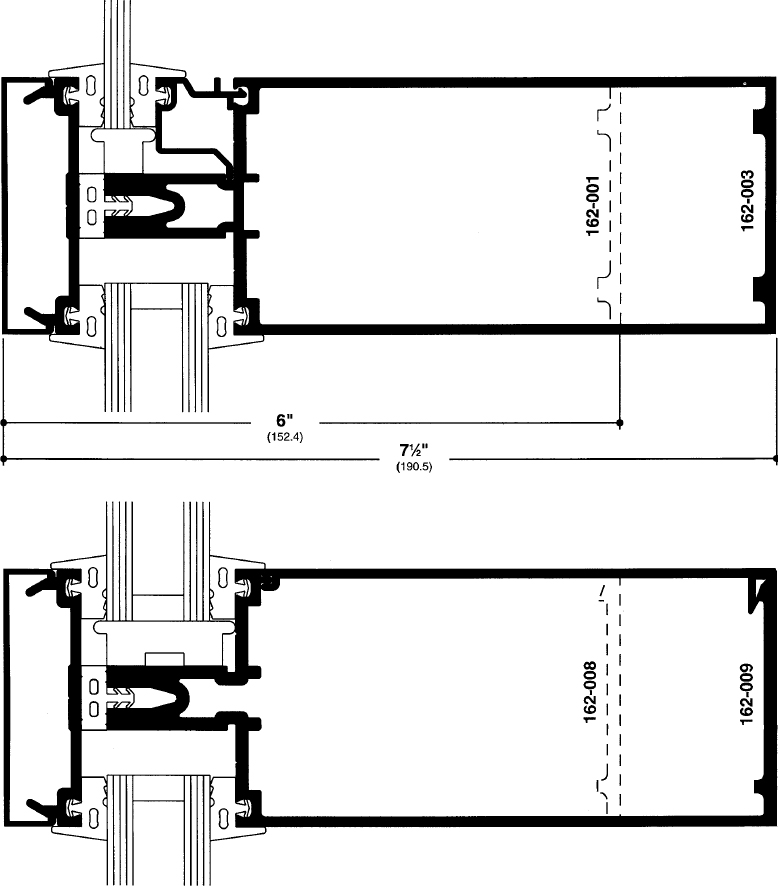
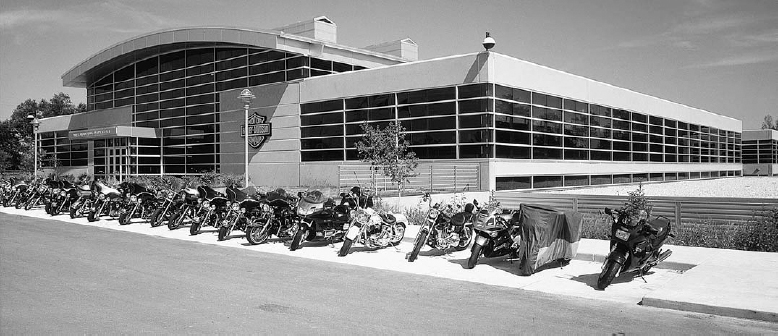
FIGURE 21.16 This building for the Harley-Davidson Motor Company in Wauwatosa, Wisconsin, features the Kawneer 1600 System1, whose details are shown in Figures 21.11–21.14.
Leave a Reply