Author: workhouse123
-

Working of Impulse Turbine
In the impulse turbine, all the pressure drops occur in nozzle and there is no pressure drop of steam passing through blades. Let us consider steam enters the nozzle with pressure of P0 and velocity of V0, after expansion of steam in nozzle pressure drops to P1 and velocity increases to V1. High velocity jet of steam impinges on the blades…
-

Impulse Turbine (de-Laval Turbine)
If torque produced on the shaft of the turbine is only due to change in momentum of steam and pressure of steam at inlet and outlet of the turbine being same, it is known as impulse turbine. In this turbine, the expansion of high-pressure steam occurs only in nozzle as shown in Figure 5.8a, b. During…
-
Classification of Steam Turbine
Broadly, steam turbine can be classified into two categories as follows: Pure reaction turbine cannot be used for practical purpose; therefore, impulse-reaction turbine is referred as reaction turbine.
-

STEAM TURBINE
Steam turbine is a prime mover, which converts heat energy of steam into mechanical energy by rotating motion of the blade. Total energy conversion involves two types of steam expansion—expansion of steam in nozzle and expansion of steam in turbine blades. The function of steam engine and steam turbine are similar, but steam engine converts…
-

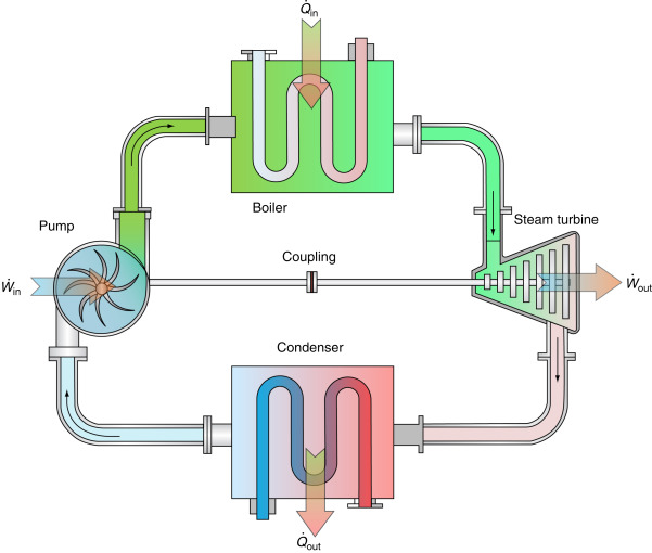
Four Processes in the Rankine Cycle
There are four important processes in the Rankine cycle. These states are identified by numbers as shown in Figure 5.6. Figure 5.6 Rankine Cycle Process 1–2 (Pumping Process): The working fluid is pumped from low pressure to high pressure, as the fluid is a liquid at this stage the pump requires some small amount of input energy. Process…
-

Actual Indicator Diagram
In this diagram, points 1, 2, 3, 4 and 5 show actual admission pressure, point of cut-off, point of release, point of closing the exhaust port and starting of compression, and point of opening of admission port, respectively. The area of actual indicator diagram is less than the theoretical indicator diagram. Figure 5.5 Actual Indicator Diagram…
-
Modified Rankine Cycle: Theoretical Indicator Diagram
Theoretical indicator diagram for a steam engine is shown in Figure 5.3 without clearance volume and with clearance volume in Figure 5.4. In Figure 5.3, clearance volume is zero. Steam at boiler pressure enters into the cylinder at point 1 and cut-off at point 2. Then the steam expands inside the cylinder isothermally from point 2 to point 3. Point 3…
-

STEAM ENGINES AND THEIR WORKING PRINCIPLES
A steam engine is a reciprocating heat engine that performs mechanical work by using steam as its working fluid. Steam engines are external combustion engines based on modified Rankine cycle, where the working fluid is separate from the combustion products. Water is heated in a boiler until it reaches a high pressure and temperature (superheated…
-

INTRODUCTION
Steam power system is a system in which the heat energy of the steam is used to produce mechanical power. Various types of fuels (coal, diesel, natural gas, geothermal, nuclear, etc.) are used to produce the high quality of steam, i.e., superheated steam and then the thermodynamic expansion process is used to convert the heat…
-

Non-renewable Energy
Over 85% of the energy used in the world is from non-renewable sources. Most of the developed nations are dependent on non-renewable energy sources such as fossil fuels (coal and oil) and nuclear power. These sources are called non-renewable because they cannot be renewed or regenerated quickly enough to keep pace with their use. Coal: Coal…