A transformer is said to be on no-load when secondary winding is open circuited and the secondary current I2 is zero. In this case, neither the secondary winding has any effect on the magnetic flux in the core nor it has any effect on the primary current.
In actual transformer, the losses cannot be neglected. Therefore, if transformer is on no-load, a small current I0 (usually 2% to 10% of the rated value) called exciting current is drawn by the primary. This current has to supply the iron losses (hysteresis and eddy current losses) in the core and a very small amount of copper loss in the primary (the primary copper losses are so small as compared to core losses that they are generally neglected moreover secondary copper losses are zero as I2 is zero).
Therefore, current Io lags behind the voltage vector V1 by an angle ɸ0 (called hysteresis angle of advance) which is less than 90°, as shown in Figure 10.13(b). The angle of lag depends upon the losses in the transformer. The no-load current I0 has two components:
- One, Iw in phase with the applied voltage V1, called active or working component. It supplies the iron losses and a small primary copper losses.
- The other, Imag in quadrature with the applied voltage V1, called reactive of magnetizing component. It produces flux in the core and does not consume any power.
From phasor (vector) diagram shown in Figure 10.13(b).
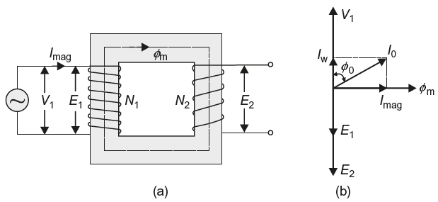
Fig. 10.13 (a) Transformer on no-load (b) Phasor diagram of transformer at no-load
Working component,
Iw = I0 cos ɸ0
Magnetizing component,
Imag = I0 sin ɸ0
No-load current,
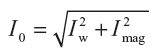
Primary p.f. at no-load,
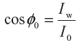
No-load power input,
P0 = V1I0 cos ɸ0
Exciting resistance,

Exciting reactance,
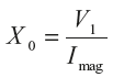
The equivalent circuit of a transformer at no-load is shown in Figure 10.14. Here, R0 represents the exciting resistance of the transformer that carries power loss component of no-load current, that is, Iw used to meet with the no-load losses in the transformer, whereas X0 represents the exciting reactance of the transformer that carries watt-less component of no-load current, that is, Imag used to set up magnetic field in the core.
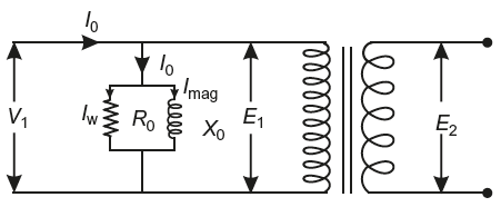
Fig. 10.14 Equivalent circuit of a transformer at no-load
Example 10.8
A 230/110 V single-phase transformer has a core loss of 100 W. If the input under no-load condition is 400 VA, find core loss current, magnetizing current, and no-load power factor angle.
Solution:
Here,
V1 = 230 V; V2 = 110 V; V2 = 110 V; Pi = 100 W
Input at no-load = 400 VA
That is,
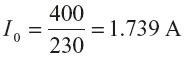
V1I0 = 400
or no-load current
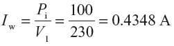
Core loss current,
Magnetizing current, ![]()
No-load power factor,
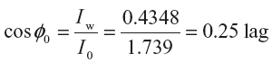
No-load power factor angle,
ɸ0 = cos−1 0.25 = 75.52°
Example 10.9
A single-phase, 50 kVA, 2300/230 V, 50 Hz transformer is connected to 230 V supply on the secondary side, the primary being open. The meter indicates the following readings:–
Power = 230 W
Voltage = 230 V
Current = 6.5 A
Find (i) core loss, (ii) loss component of the current, and (iii) magnetizing current. Draw the phasor diagram for this condition.
Solution:
Power input at no-load, P0 = 230 W
V1 = 230 V
Current at no-load,
I0 = 6.5 A
- Since low-voltage winding resistance is not given, the copper losses cannot be separated, and therefore, whole of the power input will represent the iron or core losses.∴ Core loss = 230 W
- Using relation P0 = V1J0 cosɸ0 = V1IwLoss component of current,
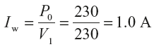
- Magnetizing current,
 Under the given condition, transformer is operated at no-load.Where V1 = 230 V; I0 = 6.5 A; Iw = 1.0 AImag = 6.423 A; E1 = 230 V; E2 = 2300 V
Example 10.10
The no-load current of a transformer is 5 A at 0.25 p.f. when supplied at 230 V, 50 Hz. The number of turns on primary winding are 200. Calculate (i) maximum value of flux in the core, (ii) core loss, (iii) magnetizing current, and (iv) exciting resistance and reactance of the transformer. Also draw its equivalent circuit.
Solution:
- Using the relation, E1 = 4.44N1 f ɸmor 230 = 4.44 × 220 × 50 × ɸm∴ Maximum value of flux ɸm = 518 m Wb
- Core loss, P0 = V1I0 cos ɸ0 = 230 × 5 × 0.25 = 287.5 W
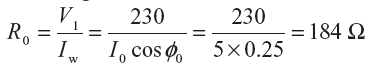
- No-load p.f., cos ɸ0 = 0.25;sin ɸ0 = sin cos−1 0.25 = 0.9682Magnetizing current component, Im = I0 sinɸ0 = 5 × 0.9682 = 4.84 AExciting resistance,
 Exciting reactance,
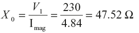
The equivalent circuit is shown in Figure 10.15. The values of different quantities are mentioned in the solution itself.
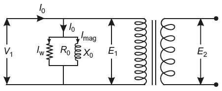
Fig. 10.15 Equivalent circuit of a transformer at no-load
At open circuit, transformer of 10 kVA, 500/250 V, 50 Hz draws a power of 167 W at 0.745 A, 500 V. Determine the magnetizing current, watt-full current, no-load power factor, hysteresis angle of advance, equivalent resistance and reactance of exciting circuit referred to primary side.
Solution:
Here,
V1 = 500 V; I0 = 0.745 A; P0 = 167 W
Watt-full component of current, 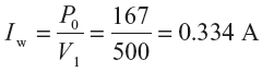
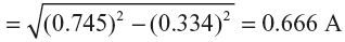
Magnetising component of current, ![]()
No-load power factor,
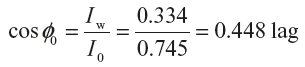
Hysteresis angle of advance,
ɸ0 = cos−1 0.448 = 63.36° lag
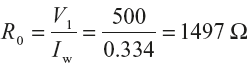
Exciting resistance,
Exciting reactance,
Leave a Reply