Author: workhouse123
-
TORQUE EQUATION
We know that when a current carrying conductor is placed in the magnetic field, a force is exerted on it that exerts turning moment or torque (F × r) (see Fig. 11.38). This torque is produced due to electromagnetic effect, and hence it is called electromagnetic torque. Fig. 11.38 Force exerted on a single conductor Let P = number of poles…
-
Significance of Back EMF
The current flowing through the armature is given by the relation: When mechanical load applied on the motor increases, its speed decreases that reduces the value of Eb. As a result, the value (V − Eb) increases that consequently increases Ia. Hence, motor draws extra current from the mains. Thus, the back emf regulates the input power as per the extra…
-
Function of a Commutator
The function of a commutator in DC motors is to reverse the direction of flow of current in each armature conductor when it passes through the MNA to obtain continuous torque. 11.16 BACK EMF It has been seen that when current is supplied to the armature conductors, as shown in Figure 11.36(a), placed in the main magnetic…
-
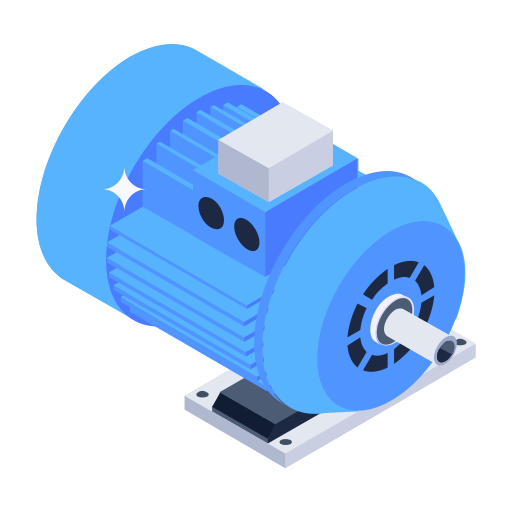
DC MOTOR
An electromechanical energy conversion device (electrical machine) that converts DC electrical energy or power (EI) into mechanical energy or power (ωT) is called a DC motor. Electric motors are used for driving industrial machines such as hammers, presses, drilling machines, lathes, rollers in paper and steel industry, and blowers for furnaces and domestic appliances such…
-
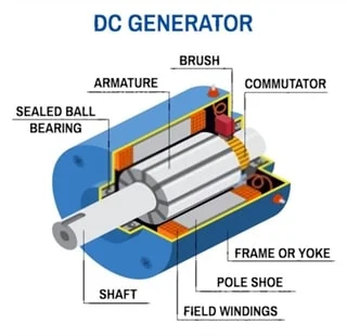
CRITICAL FIELD RESISTANCE OF A DC SHUNT GENERATOR
The open-circuit characteristic of a DC shunt generator are shown in Figure 11.31. The line OX is drawn in such a way that its slope gives the field winding resistance, i.e., Fig. 11.31 Representation of critical resistance In this case, the generator can build up a maximum voltage OB with a shunt field resistance Rsh. A line OY represents a…
-
VOLTAGE BUILD-UP IN SHUNT GENERATORS
The shunt generator is a self-excited DC generator whose field winding is supplied with the current from the output of the generator itself. However, question arises how it can supply current to the field winding before the voltage being generated? And if the field current is not supplied, how can the voltage be generated? Let…
-
Cumulative and Differential Compound-wound Generators
In compound-wound DC generators, the field is produced by the shunt as well as series winding. Generally, the shunt field is stronger than the series field. When the series field assist the shunt field, the generator is called as cumulative compound-wound generator (see Fig. 11.21(a)). However, when the series field opposes the shunt field, the generator…
-
SELF-EXCITED DC GENERATORS
A DC generator whose field winding is excited by the current supplied by the generator itself is called a self-excited DC generator. In a self-excited DC generator, the field coils may be connected in parallel with the armature, in series with the armature or partly in series, and partly in parallel with the armature winding.…
-

SEPARATELY EXCITED DC GENERATORS
A DC generator in which current is supplied to the field winding from an external DC source is called a separately excited DC generator. The flux produced by the poles depends upon the field current with in the unsaturated region of magnetic material of the poles (i.e., ɸ ∝ If), but in the saturated region, the flux remains…
-
SIMPLE LOOP GENERATOR AND FUNCTION OF COMMUTATOR
For simplicity, consider only one coil AB placed in the strong magnetic field. The two ends of the coil are joined to slip rings A′ and B′, respectively. Two brushes rest on these slip rings, as shown in Figure 11.10. Fig. 11.10 Direction of induced emf/current in internal and external circuit of rotating coil at different instants…